Creating documentation of a designed structure (drawings) may be divided into the following stages:
- Defining or loading a structure model
A structure model may be defined in Autodesk AutoCAD Structural Detailing - Steel. It is also possible to prepare it in another program and open in Autodesk AutoCAD Structural Detailing - Steel (see: Autodesk AutoCAD Structural Detailing - Robot link).
Drawings will be prepared for 3D elements of a real 3D structure.
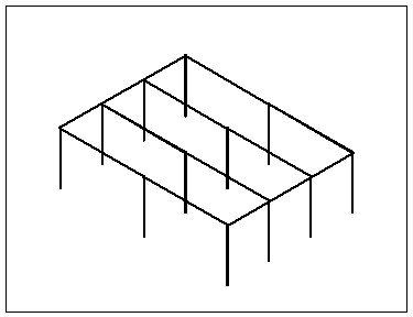
All operations are performed in the model layout, which is an AutoCAD® object used when working with a structure model.
- Assigning positions to structure elements
A position is an object concerned with organization of structure model elements. A position is assigned to one or several structure elements, for which a common set of drawings may be generated.
Assigning positions is available on the Model and Parts Edition tabs of the Object inspector dialog. Positions defined are displayed on the Positions tab.
- Defining documents
A document is a set of drawings for a position (for each position, any number of documents may be generated). A document consists of views, but cannot be printed.
Documents are generated based on templates, which are predefined sets of views composing a logical whole (for example, 3 projections of a given object). A template determines which drawings (projections or sections) should be included in a document.
All operations are performed in edition layouts.
The edition layout is an AutoCAD® object. Only one document may be active at a time and only this document may be edited in the edition layout. You should not print the contents of the edition layout.
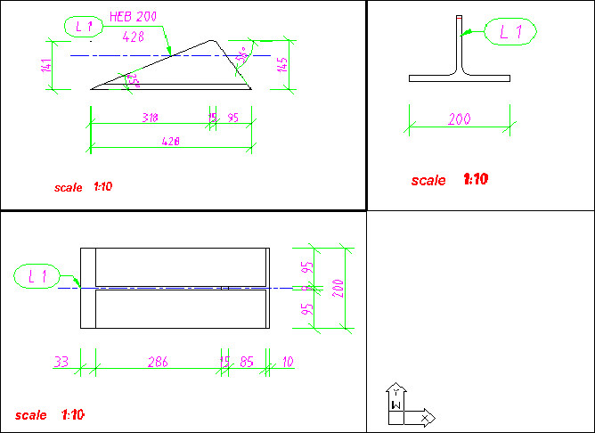
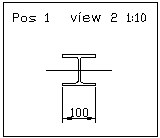
- Defining (editing) views/projections
A view is a single drawing that always constitutes a document component; if it has been added to a printout, it is simultaneously a printout element . Only a view (drawing) contained in a printout may be printed.
Projections of assemblies are prepared based on the coordinate system of the main part (by default it is the longest part of an assembly). The coordinate system of assemblies (and plates) can be modified using the Change coordinate system option (on the Positions tab in the Object inspector). You can select one of the following options for assemblies: UCS, WCS, Main Part and 3Points (or UCS, WCS and 3Points for plates). Drawings created after this modification show assemblies in a selected coordinate system. Drawings created before this modification should be updated (using the Update documents option on the Positions tab in the Object inspector).
Edition is performed in the edition layout.
- Generating a printout
A printout consists of views (for each Printout there is exactly one layout corresponding to it).
All operations are performed in printout layouts.
The printout layout is an AutoCAD® object. It is used for composition of a final printout. For each printout layout, there is one printout.
See also:
Example of creating documents and insertion of documents in a drawing