All the options available in Autodesk AutoCAD Structural Detailing - Reinforcement are presented below. The following information is included:
- Position of the option in the text menu,
- Position of the option in the ribbon,
- The icon symbolizing the option,
- Command activating the option from the command line,
- Short description of the option.
See also: Ribbon.
|
Reinforcement - elevation |
Opens the Reinforcement - elevation dialog; the option defines the reinforcing bars (longitudinal reinforcement) in an element of an RC structure. Menu: Reinforcement > Reinforcement - elevation Ribbon: ASD - Reinforcement > Reinforcement - definition > Reinforcement - elevation Toolbar: Definition-bars > Reinforcement - elevation Command line: RBCR_DEF_BAR_BV |
|
Reinforcement - cross-section |
Opens the Reinforcement - cross-section dialog; the option defines reinforcing bars (transversal reinforcement) in a cross-section of an RC structure element. Menu: Reinforcement > Reinforcement - section Ribbon: ASD - Reinforcement > Reinforcement - definition > Reinforcement - section Toolbar: Definition-bars > Reinforcement - section Command line: RBCR_DEF_BAR_BS |
|
Special stirrups |
Opens the Special stirrups dialog; this option defines special stirrups (transversal reinforcement) in the cross-section of an RC structure element. Menu: Reinforcement > Special stirrups Ribbon: ASD - Reinforcement > Reinforcement - definition > Special stirrups Toolbar: Definition-bars > Special stirrups Command line: RBCR_DEF_STIRRUP_SPEC |
|
Reinforcement- point |
Opens the Reinforcement- point dialog; the option defines the distribution of reinforcement which is presented as points (reinforcement n cross-section). Menu: Reinforcement > Reinforcement - point Ribbon: ASD - Reinforcement > Reinforcement - definition > Reinforcement - point Toolbar: Definition-bars > Reinforcement point Command line: RBCR_DISTRIBUTION_POINT |
|
Special reinforcement |
Opens the Special reinforcement dialog; the option defines particular reinforcing bars used in different elements of RC structures (e.g. crest-shaped reinforcement, corbel reinforcement, transport handles, etc.). Menu: Reinforcement > Special reinforcement Ribbon: ASD - Reinforcement > Reinforcement - definition > Special reinforcement Toolbar: Definition-bars > Special reinforcement Command line: RBCR_DEF_BARLIBSPECIAL |
|
Wire fabrics in cross section |
Opens the Wire Fabric Shape dialog; the option defines a wire fabric in the cross section of an RC structure element. Menu: Reinforcement > Wire fabrics in cross section Ribbon: ASD - Reinforcement > Reinforcement - definition > Wire fabrics in cross section Toolabar: Definition-wire fabrics > Wire fabrics in cross section Command line: RBCR_DEF_NET_SIDE |
|
Wire fabrics in cross section - symbol
|
The option presents an indicated wire fabric in cross section outside the formwork contour to show a full shape and geometry of a reinforcement (this is a detailed presentation of a wire fabric needed for a bar bender to shape the reinforcement properly). Menu: Reinforcement > Wire fabrics in cross section - symbol Ribbon: ASD - Reinforcement > Reinforcement - definition > Wire fabrics in cross section - symbol Toolbar: Definition-wire fabrics > Wire fabrics in cross section - symbol Command line: RBCR_DEF_NET_PULL |
|
Reinforcement bars - legend |
The option presents an indicated bar outside the formwork contour to show the whole reinforcement shape and geometry (it is a detailed bar presentation needed for a bar bender to shape reinforcement properly). Menu: Reinforcement > Reinforcement - bar legend Ribbon: ASD - Reinforcement > Reinforcement - definition > Reinforcement bars - legend Toolbar: Definition-bars > Reinforcement bars - legend Command line: RBCR_DEF_PULL |
|
Reinforcement distribution |
The option defines reinforcement distribution. Menu: Reinforcement > Reinforcement distribution Ribbon: ASD - Reinforcement > Reinforcement - definition > Reinforcement distribution Toolbar: Definition-bars > Reinforcement distribution Command line: RBCR_DISTRIBUTION |
|
Surface reinforcement - wire fabrics |
Opens the Surface reinforcement distribution - wire fabrics dialog; the option defines regions of wire fabric distribution (e.g. reinforcement of RC plates). Menu: Reinforcement > Surface reinforcement - wire fabrics Ribbon: ASD - Reinforcement > Reinforcement - definition > Surface reinforcement - wire fabrics Toolbar: Definition-bars > Surface reinforcement-wire fabrics Command line: RBCR_NETD_RECT |
|
Surface reinforcement - bars |
Opens the Surface reinforcement - bars dialog; the option defines regions of bar distribution (e.g. reinforcement of RC slabs). Menu: Reinforcement > Surface reinforcement - bars Ribbon: ASD - Reinforcement > Reinforcement - definition > Surface reinforcement - bars Toolbar: Definition-bars > Surface reinforcement - bars Command line: RBCR_DEF_BAR_SURF |
|
Radial reinforcement - bars |
Opens the Radial surface reinforcement dialog; the option defines radial reinforcement (e.g. reinforcement of round RC slabs). Menu: Reinforcement > Radial distribution Ribbon: ASD - Reinforcement > Reinforcement - definition > Radial reinforcement - bars Toolbar: Definition-bars > Radial reinforcement - bars Command line: RBCR_CREATE_RADIAL |
|
Wire fabrics distribution |
Opens the Surface reinforcement distribution - wire fabrics dialog; the option defines regions of wire fabric distribution (e.g. reinforcement of RC slabs). Menu: Reinforcement > Distribution - wire fabrics Ribbon: ASD - Reinforcement > Reinforcement - definition > Wire fabrics disctribution Toolbar: Definition-wire fabrics > Wire fabrics distribution Command line:RBCR_NS_DISTRIBUTION |
|
Steel profiles - definition |
|
|
Steel profiles |
Opens the Steel profiles dialog; the option defines steel profiles. Menu: Reinforcement > Definition - steel profiles > Steel profiles Ribbon: ASD - Reinforcement > Reinforcement - definition > Steel profiles Toolbar: Definition - steel profiles > Steel profiles Command line:RBCR_CREATE_STEEL_VIEW |
|
Steel profiles - description |
Opens the Profile description dialog; the option defines the indicated steel profile. Menu: Reinforcement > Definition - steel profiles > Steel profiles - description Ribbon: ASD - Reinforcement > Reinforcement - definition > Steel profiles - description Toolbar: Definition - steel profiles > Steel profiles - description Command line: RBCR_CREATE_STEEL_DESC |
|
Steel profiles - section |
Selecting this option results in generation of a steel profile section; to create a vertical section, indicate a cutting line (two points defining a segment) and a section ‘depth’. Menu: Reinforcement > Definition - steel profiles > Steel profiles - section Ribbon: ASD - Reinforcement > Reinforcement - definition > Steel profiles - section Toolbar: Definition - steel profiles > Steel profiles - section Command line: RBCR_CREATE_STEEL_SECTION |
|
Cut profile to line |
The option enables cutting a steel profile so that it fits a plane defined by the line. Menu: Reinforcement > Definition - steel profiles > Cut profile to line Ribbon: ASD - Reinforcement > Reinforcement - definition > Cut profile to line Toolbar: Definition - steel profiles > Cut profile to line Command line: RBCR_CREATE_STEEL_CUT |
|
Delete cut |
The option deletes a cut from a created steel profile. Menu: Reinforcement > Definition - steel profiles > Delete cut Ribbon: ASD - Reinforcement > Reinforcement - definition > Delete cut Toolbar: Definition - steel profiles > Delete cut Command line: RBCR_CREATE_STEEL_CUTS |
|
Reinforcement description |
|
|
Bar description |
The option describes a reinforcing bar. Menu: Reinforcement > Reinforcement description > Bar description Ribbon: ASD - Reinforcement > Reinforcement - definition > Bar description Toolbar: Definition-bars > Bar description Command line: RBCR_BARBVFORMDESC |
|
Reinforcement distribution description |
The option defines reinforcement distribution. Menu: Reinforcement > Reinforcement description > Reinforcement distribution description Ribbon: ASD - Reinforcement > Reinforcement - definition > Reinforcement distribution description Toolbar: Definition-bars > Reinforcement distribution description Command line: RBCR_DISTRIB_DESC |
|
Bar end symbol |
The option defines a symbol of bar ends. Menu: Reinforcement > Reinforcement description > Bar end symbol Ribbon: ASD - Reinforcement > Reinforcement - definition > Bar end symbol Toolbar: Definition-bars > Bar end symbol Command line: RBCR_BAR_END |
|
Description of wire fabric in cross section
|
The option defines a wire fabric in the cross section. Menu: Reinforcement > Reinforcement description > Description of wire fabric in cross section Ribbon: ASD - Reinforcement > Reinforcement - definition > Description of wire fabric in cross section Toolbar: Definition-wire fabrics > Description of wire fabric in cross section Command line: RBCR_DEF_NET_SIDE_DESC |
|
Styles of reinforcement description |
Opens the Description of reinforcement shape dialog; the option allows defining description styles (format) for individual elements of reinforcement. Menu: Reinforcement > Reinforcement description > Styles of reinforcement description command Ribbon: ASD - Reinforcement > Settings > Styles of reinforcement description Command line: RBCR_SHAPE_DESCR |
|
Reinforcement tables |
|
|
Bars - Main table |
The option adds a main table for reinforcing bars presented in a drawing at a point in the drawing. Menu: Reinforcement > Reinforcement tables > Bars - Main table Ribbon: ASD - Reinforcement > Reinforcement table > Bars - Main table Toolbar: Reinforcement table > Bars - Main table Command line: RBCR_LIST_BAR_MAIN |
|
Bars - Element table |
The option creates a reinforcement table which presents reinforcing bars divided into structural elements (beams, columns, etc.). Menu: Reinforcement > Reinforcement table > Bars - Element table Ribbon: ASD - Reinforcement > Reinforcement table > Bars - Element table Toolbar: Reinforcement table > Bars - Element table Command line: RBCR_LIST_BAR_ELEM |
|
Bars - Detailed table |
The option adds a detailed table for a reinforcement position with variable distribution or with bar surface distribution provided in a drawing. Menu: Reinforcement > Reinforcement table > Bars - Detailed table Ribbon: ASD - Reinforcement > Reinforcement tables > Bars - Detailed table Toolbar: Reinforcement tables > Bars - Detailed table Command line: RBCR_LIST_BAR_DETA |
|
Bars - Summary table |
The option adds a summary table for reinforcing bars presented in a drawing. Menu: Reinforcement > Reinforcement table > Bars - Summary table Ribbon: ASD - Reinforcement > Reinforcement tables > Bars - Summary table Toolbar: Reinforcement tables > Bars - Summary table Command line: RBCR_LIST_BAR_SUM |
|
Wire fabrics - Main table |
The option adds a main table for wire fabrics presented in a drawing. Menu: Reinforcement > Reinforcement table > Wire fabrics - Main table Ribbon: ASD - Reinforcement > Reinforcement tables > Wire fabrics - Main table Toolbar: Reinforcement tables > Wire fabrics - Main table Command line: RBCR_LIST_NET_MAIN |
|
Wire fabrics - Summary table |
The option adds a summary table for wire fabrics presented in a drawing. Menu: Reinforcement > Reinforcement table > Wire fabrics - Summary table Ribbon: ASD - Reinforcement > Reinforcement tables > Wire fabrics - Summary table Toolbar: Reinforcement tables > Wire fabrics - Summary table Command line: RBCR_LIST_NET_SUM |
|
Update - reinforcement tables |
The option updates the selected table after making changes in reinforcement geometry/parameters. Menu: Reinforcement > Reinforcement table > Update - reinforcement tables Ribbon: ASD - Reinforcement > Reinforcement table > Update - reinforcement tables Toolbar: Reinforcement table > Update - reinforcement tables Command line: RBCR_LIST_ACT |
|
Table Printout/Export/Edit |
The option prints or exports a table of the indicated reinforcement to an *.xls or *.csv format file. Menu: Reinforcement > Reinforcement table > Table Printout/Export/Edit Ribbon: ASD - Reinforcement > Reinforcement table > Printout/Export/Edit Toolbar: Reinforcement table > Printout/Export/Edit Command line: RBCR_LIST_EXP |
|
Styles - reinforcement tables |
Opens the Reinforcement tables - style manager dialog; the option defines/modifies styles of the reinforcement tables applied to prepare a reinforcement table for RC structure elements. Menu: Reinforcement > Reinforcement table > Styles - reinforcement tables Ribbon: ASD - Reinforcement > Reinforcement table > Printout/Export/Table edit Command line: RBCR_LIST_PAR |
|
Insert drawing from Autodesk Robot Structural Analysis  |
The option inserts a drawing prepared in Autodesk Robot Structural Analysis. Menu: Reinforcement > Insert drawing from Robot Ribbon: ASD - Reinforcement > Tools > Insert drawing from Robot Toolbar: Definition-bars > Insert drawing from Robot Command line: RBCR_TOOL_IMPORT_RM |
|
Reinforcement areas from Autodesk Robot Structural Analysis |
The option reads values of required (theoretical) reinforcement areas calculated for a plate in Autodesk Robot Structural Analysis. A Robot file (*.rtd) is read, providing values of top and bottom reinforcement for every finite element on the plate. After opening the file in Autodesk AutoCAD Structural Detailing plate reinforcement is presented in a form of crosses which disappear once the appropriate plate reinforcement is generated in Autodesk AutoCAD Structural Detailing. Menu: Reinforcement > Reinforcement areas from Robot Ribbon: ASD - Reinforcement > Tools > Reinforcement areas from Robot Toolbar: Definition-bars > Reinforcement areas from Robot Command line: RBCR_TOOL_IMPORT_PL |
|
Structure elements - reinforcement |
Submenu with commands to define reinforcement of typical elements of RC structures. |
|
Spread footing |
The option defines reinforcement of a typical spread footing once several characteristic parameters are determined in the dialog (spread footing geometry/reinforcement parameters). Menu: Reinforcement > Structure elements - reinforcement > Spreat footing Ribbon: ASD - Structure elements > Structure elements - reinforcement > Spread footing Toolbar: Structure elements - reinforcement > Spread footing |
|
Sleeve footing |
The option defines reinforcement of a typical sleeve footing once several characteristic parameters are determined in the dialog (footing geometry/reinforcement parameters). Menu: Reinforcement > Typical structures - reinforcement > Structure elements - reinforcement > Sleeve footing Ribbon: ASD Structure elements > Structure elements - reinforcement > Sleeve footing Toolbar: Structure elements - reinforcement > Sleeve footing |
|
Continuous footing |
The option defines reinforcement of a typical continuous footing once several characteristic parameters are determined in the dialog (continuous footing geometry/reinforcement parameters). Menu: Reinforcement > Structure elements - reinforcement > Continuous footing Ribbon: ASD - Structure elements > Structure elements - reinforcement > Continuous footing Toolbar: Structure elements - reinforcement > Continuous footing |
|
Column |
The option defines reinforcement of a typical column - circular or rectangular, once several characteristic parameters are determined in the dialog (column geometry/reinforcement parameters). Menu: Reinforcement > Structure elements - reinforcement > Column Ribbon: ASD - Structure elements > Structure elements - reinforcement > Column Toolbar: Structure elements - reinforcement > Column |
|
Opening |
The option defines reinforcement of a typical opening - circular or rectangular, once several characteristic parameters are determined in the dialog (opening geometry/reinforcement parameters). Menu: Reinforcement > Structure elements - reinforcement > Opening Ribbon: ASD - Structure elements > Structure elements - reinforcement > Opening Toolbar: Structure elements - reinforcement > Opening |
|
Corner |
The option derfines reinforcement of a typical corner once several characteristic parameters are determined in the dialog (corner geometry/reinforcement parameters). Menu: Reinforcement > Structure elements - reinforcement > Corner Ribbon: ASD - Structure elements > Structure elements > reinforcement > Corner Toolbar: Structure elements > reinforcement > Corner |
|
Slab corner |
The option defines reinforcement of a typical RC slab corner after specifying a few characteristic parameters in the dialog (slab corner geometry / reinforcement parameters). Menu: Reinforcement > Structure elements - reinforcement > Slab corner Ribbon: ASD - Structure elements > Structure elements - reinforcement > Slab corner Toolbar: Structure elements - reinforcement > Slab corner |
|
Distribution of prefabricated slabs |
The option derfines distribution of prefabricated slabs and generating reinforcement for these slabs after specifying several characteristic parameters in the dialog (geometry of the slab distribution region/ reinforcement parameters). Menu: Reinforcement > Structure elements - reinforcement > Distribution of prefabricated slabs Ribbon: ASD - Structure elements > Structure elements - reinforcement > Distribution of prefabricated slabs Toolbar: Structure elements - reinforcement > Distribution of prefabricated slabs |
|
Beam |
The option defines typical beam reinforcement after specifying a few characteristic parameters in the dialog (beam geometry / reinforcement parameters). Menu: Reinforcement > Structure elements - reinforcement > Beam Ribbon: ASD - Structure elements > Structure elements - reinforcement > Beam Toolbar: Structure elements - reinforcement > Beam |
|
Stairs |
The option defines typical stair reinforcement after specifying a few characteristic parameters in the dialog (stair geometry / reinforcement parameters). Menu: Reinforcement > Structure elements - reinforcement > Stairs Ribbon: ASD - Structure elements > Structure elements - reinforcement > Stairs Toolbar: Structure elements - reinforcement > Stairs |
|
Pile cap |
The option defines typical reinforcement of a pile cap (pile foundation) after specifying a few characteristic parameters in the dialog (pile cap geometry / reinforcement parameters). Menu: Reinforcement > Structure elements - reinforcement > Pile cap Ribbon: ASD - Structure elements > Structure elements - reinforcement > Pile cap Toolbar: Structure elements - reinforcement > Pile cap |
|
Pile |
The option defines reinforcement of a typical pile of pile foundation after specifying a few characteristic parameters in the dialog (pile geometry / reinforcement parameters). Menu: Reinforcement > Structure elements - reinforcement > Pile Ribbon: ASD - Structure elements > Structure elements - reinforcement > Pile Toolbar: Structure elements - reinforcement > Pile |
|
Retaining wall |
The option enables defining reinforcement of a typical retaining wall after providing several characteristic parameters in the dialog (retaining wall geometry/reinforcement parameters) Menu: Reinforcement > Structure elements - reinforcement > Retaining wall Ribbon: ASD - Structure elements > Structure elements - reinforcement > Retaining wall Toolbar: Structure elements - reinforcement > Retaining wall |
|
Ground beam |
The option defines typical reinforcement of a ground beam after specifying a few characteristic parameters in the dialog (beam geometry / reinforcement parameters). Menu: Reinforcement > Structure elements - reinforcement > Ground beam Ribbon: ASD - Structure elements > Structure elements - reinforcement > Ground beam Toolbar: Structure elements - reinforcement > Ground beam |
|
Parapet |
The option defines typical reinforcement of a parapet after specifying a few characteristic parameters in the dialog (parapet geometry / reinforcement parameters). Menu: Reinforcement > Structure elements - reinforcement > Parapet Ribbon: ASD - Structure elements > Structure elements - reinforcement > Parapet Toolbar: Structure elements - reinforcement > Parapet |
|
Create linear element |
The option defines the RC structure element (section of an RC element) that is assigned the element length. Once selected, the following dialog displays: 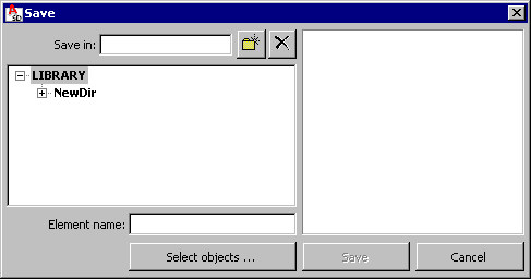 After clicking Select objects, the element (a block of drawing elements) displays. Such an element may be saved to the database. Menu: Reinforcement > Structure elements - reinforcement > Create linear element Ribbon: ASD - Structure elements > Structure elements - reinforcement > Create linear element Toolbar: Structure elements - reinforcement > Create linear element |
|
Insert linear element |
The option inserts the RC structure element (section of an RC element) that has been assigned the length. Once selected, the following dialog displays: 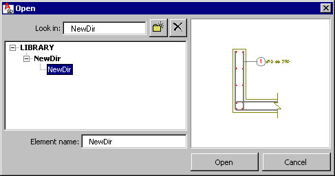 After selecting a saved linear element, a block of drawing elements is placed in a drawing. The linear element chosen is assigned name and length; the spacing of elements over the length (e.g. 3 meters of length with spacing every 20 cm) is also specified. Menu: Reinforcement > Structure elements - reinforcement > Insert linear element Ribbon: ASD - Structure elements > Structure elements - reinforcement > Insert linear element Toolbar: Structure elements - reinforcement > Insert linear element |
|
Structure elements -formworks |
Submenu with commands which define the formwork of typical elements of RC structures. |
|
Spread footing |
The option derfines the formwork of a typical spread footing after providing several characteristic parameters in the dialog (spread footing geometry). Menu: Reinforcement > Formwork > Spread footing Ribbon: ASD - Structure elements > Structure elements - formwork > Spread footing Toolbar: Structure elements - formwork > Spread footing |
|
Continuous footing |
The option defines the formwork of a typical continuous footing after providing several characteristic parameters in the dialog (continuous footing geometry). Menu: Reinforcement > Structure elements - formwork > Continuous footing Ribbon: ASD - Structure elements > Structure elements - formwork > Continuous footing Toolbar: Structure elements - formwork > Continuous footing |
|
Sleeve footing |
The option enables defining reinforcement of a typical sleeve footing after providing several characteristic parameters in the dialog (sleeve footing geometry) Menu: Reinforcement > Structure elements - formwork > Sleeve footing Ribbon: ASD - Structure elements > Structure elements - formwork > Sleeve footing Toolbar: Structure elements - formwork > Sleeve footing |
|
Column |
The option defines the formwork of a typical column after providing several characteristic parameters in the dialog (column geometry). Menu: Reinforcement > Structure elements - formwork > Column Ribbon: ASD - Structure elements > Structure elements - formwork > Column Toolbar: Structure elements - formwork > Columns |
|
Beam |
The option defines the formwork of a typical beam after providing several characteristic parameters in the dialog (beam geometry). Menu: Reinforcement > Structure elements - formwork > Beam Ribbon: ASD - Structure elements > Structure elements - formwork > Beam Toolbar: Structure elements - formwork > Beam |
|
Stairs |
The option defines the formwork of typical stairs after providing several characteristic parameters in the dialog (geometry of stairs). Menu: Reinforcement > Structure elements - formwork > Stairs Ribbon: ASD - Structure elements > Structure elements - formworks > Stairs Toolbar: Structure elements - formwork > Stairs |
|
Pile cap |
The option defines the formwork of a typical pile cap (pile foundation) after providing several characteristic parameters in the dialog (pile cap geometry). Menu: Reinforcement > Structure elements - formwork > Pile cap Ribbon: ASD - Structure elements > Structure elements - formwork > Pile cap Toolbar: Structure elements - formwork > Pile cap |
|
Ground beam |
The option defines the formwork of a typical ground beam after providing several characteristic parameters in the dialog (beam geometry). Menu: Reinforcement > Structure elements - formwork > Ground beam Ribbon: ASD - Structure elements > Structure elements - formwork > Ground beam Toolbar: Structure elements - formwork > Ground beam |
|
Parapet |
The option defines the formwork of a typical parapet after providing several characteristic parameters in the dialog (parapet geometry). Menu: Reinforcement > Structure elements - formwork > Parapet Ribbon: ASD - Structure elements > Structure elements - formwork > Parapet Toolbar: Structure elements - formwork > Parapet |
|
Retaining wall |
The option enables defining formworks of a typical retaining wall after providing several characteristic parameters in the dialog (retaining wall geometry). Menu: Reinforcement > Structure elements - formwork > Retaining wall Ribbon: ASD - Structure elements > Structure elements - formwork > Retaining wall Toolbar: Structure elements - formwork > Retaining wall |
|
Additional connecting elements |
The option enables inserting additional connecting elements in the drawing (e.g. bolts, anchors). Menu: Reinforcement > Structure elements - formwork > Additional connecting elements Ribbon: ASD - Structure elements > Structure elements - formwork > Additional connecting elements Toolbar: Structure elements - formwork > Additional connecting elements |
|
Use 3D solids  |
The option enables transforming 3D solid objects with an untypical shape, into ASD typical element. These new 3D elements will only consist of a formwork and be created for 4 types of elements: beam, column, spread footing and user element. Menu: Reinforcement > Structure elements - formwork > Use 3D solids Ribbon: ASD - Structure elements > Structure elements - formwork > Use 3D solids Toolbar: Structure elements - formwork > Use 3D solids |
|
Tools |
|
|
Set scale of reinforcement description |
The option chnages the scale of reinforcement description; once this option has been applied, the drawing displayed on the Model tab shows no changes, because modification of the scale is presented while generating a printout (a final drawing) on printout layouts. Menu: Reinforcement > Tools > Set scale of reinforcement description Ribbon: ASD - Reinforcement > Modify > Set scale of reinforcement description Toolbar: Tool > Set scale of reinforcement description Command line: RBCR_DESC_SCALE |
|
Create projection plane |
The option defines a view used during generation of a final drawing; while generating a projection plane, the scale should be specified. Menu: Reinforcement > Tools > Create projection plane Ribbon: ASD - Reinforcement > Tools > Create projection plane Toolbar: Tools > Create projection plane Command line: RBCT_ADDVIEW |
|
Element manager |
The option divides the reinforcing bars into structural elements (beams, columns, etc.). Menu: Reinforcement > Tools > Element manager Ribbon: ASD - Reinforcement > Tools > Element manager Toolbar: Tools > Element manager Command line: RBCR_CREATE_ELEMENT See also: |
|
Create cross-section |
The option creates a cross-section; to create a cross-section, select an object, cutting line (two points defining a segment) and cross-section ‘depth’. Use this option for surface and linear distributions. Menu: Reinforcement > Tools > Create cross-section Ribbon: ASD - Reinforcement > Tools > Create cross-section Toolbar: Tools > Create cross-section Command line: RBCR_CREATE_ELSECTION |
|
Copy view |
The option copies a selected view. You can use this option for views (of cross-sections, for example) in which top / bottom reinforcement of a slab is displayed. Copied views are mutually linked. Menu: Reinforcement > Tools > Copy view Ribbon: ASD - Reinforcement > Tools > Copy view Toolbar: Tools > Copy view Command line: RBCR_COPY_VIEW |
|
Edit bar / wire fabric database |
The option edits databases of reinforcing bars and wire fabrics (modifying parameters of bars or wire fabrics, adding new ones). Menu: Reinforcement > Tools > Edit bar > wire fabric database Ribbon: ASD - Reinforcement > Modify > Edit bar/wire fabric database Command line: RBCR_TOOL_DBEDIT |
|
Multiple reinforcements |
The option defines multiple selected reinforcement (the reinforcement quantity in a structure); the value specified is provided in the reinforcement summary table (in the Number of elements column). Menu: Reinforcement > Tools > Multiple reinforcements Ribbon: ASD - Reinforcement > Modify > Multiple reinforcements Toolbar: Modify > Multiple reinforcements Command line: RBCR_TOOL_QUANTN |
|
Reinforcement - information |
The option displays basic information concerning indicated reinforcing bar or reinforcement distribution. Menu: Reinforcement > Tools > Reinforcement - information Ribbon: ASD - Reinforcement > Tools > Reinforcement - information Toolbar: Tools > Reinforcement - information Command line: RBCR_TOOL_INFO |
|
Renumbering of reinforcement position |
The option changes the reinforcement numbering; the following elements (assigned to the bar shape) are considered during renumbering: spacing description, bar description placed outside the formwork contour, reinforcement tables, etc. Menu: Reinforcement > Tools > Renumbering of reinforcement position Ribbon: ASD - Reinforcement > Tools > Renumbering of reinforcement position Toolbar: Tools > Renumbering of reinforcement position Command line: RBCR_TOOL_RENUM |
|
Find reinforcement |
The option finds a reinforcement position in a generated drawing. Menu: Reinforcement > Tools > Find reinforcement Ribbon: ASD - Reinforcement > Tools > Find reinforcement Toolbar: Tools > Find reinforcement Command line: RBCR_TOOL_FINDR |
|
Show reinforcement without description |
The option marks (highlighting on the screen) the reinforcement for which a description has not been generated. Menu: Reinforcement -> Tools ->Show reinforcement without description Ribbon: ASD > Reinforcement > Tools > Show reinforcement without description Command line: RBCR_TOOL_SELNDSC |
|
Add lap splices |
The option automatically generates lap splices for point reinforcement bars that are not assigned a shape (only their length is defined) and whose length exceeds the commercial length of reinforcing bars (for example 12 m). Bar lap splices are generated in accordance with options for lap splices of reinforcing bars on the Codes / Materials tab in the Job Preferences dialog. Menu: Reinforcement >Tools > Add lap splices Ribbon: ASD - Reinforcement > Tools > Add lap splices Command line: RBCR_DISTRIBUTION_POINT_ADD_LAP |
|
Explode |
The option explodes some of the composed objects into individual elements. Menu: Reinforcement > Tools > Explode Ribbon: ASD - Reinforcement > Tools > Explode Toolbar: Tools > Explode Command line: RBCR_EXPLODE |
|
Reinforcement calculator |
The option opens the Reinforcement calculator dialog. Bar diameters and reinforcement areas are given in units that have been selected in Preferences. The calculator enables calculation of the following quantities:
Menu: Reinforcement > Tools > Reinforcement calculator Ribbon: ASD - Reinforcement > Tools > Reinforcement calculator Toolbar: Tools > Reinforcement calculator Command line: RBCR_TOOL_CALCULATOR |
|
Save model in dwg format  |
The option saves a model of a structure element in a DWG format file. It allows opening a file in the AutoCAD® program and carrying out further operations on a generated drawing. Note: If a drawing is saved in a *.DWG format file, and next opened in AutoCAD® on a computer where Autodesk AutoCAD Structural Detailing - Reinforcement is NOT installed, then diameter symbols will not be displayed. For diameter symbols to be displayed, you must copy the diam.sex file to the appropriate AutoCAD folder (the file has to be copied to the folder to which the path is set in the AutoCAD® program).
Menu: Reinforcement > Tools > Save model in dwg format Ribbon: ASD - Reinforcement > Tools > Save model in dwg format Toolbar: Tools > Save model in dwg format Command line: RBCT_MODELEXPORT |
|
Graphic elements |
|
|
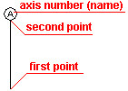
Insert axis |
The option inserts an axis to a selected place in a drawing. Symbols are drawn according to the default style set in the Job Preferences dialog. To insert a symbol of a structural axis in a drawing, do as follows:
The axis number is proposed according to the settings in the default style; while inserting the axis any number may be typed (every next one will be inserted according to the recently-applied numbering). The axis number may be modified using the context menu option. See also: Styles of symbols Menu: Reinforcement > Graphic elements > Insert axis Ribbon: ASD - Reinforcement > Graphic elements > Insert axis Toolbar: Graphic elements > Insert axis Command line: RBCT_DEF_SYMBOL_AXIS |
|
Insert section symbol |
The option inserts a section symbol to a selected place in a drawing. Symbols are drawn according to the default style set in the Job Preferences dialog. To insert a section symbol in a drawing, do as follows:
Profile numbering is proposed according to the settings in the default style; while inserting section symbols any number may be typed (every next one will be inserted according to the recently-applied numbering). The section symbol may be modified using the context menu option. See also: Styles of symbols Menu: Reinforcement > Graphic elements > Insert section symbol Ribbon: ASD - Reinforcement > Graphic elements > Insert section symbol Toolbar: Graphic elements > Insert section symbol Command line: RBCT_DEF_SYMBOL_SECTION |
|
Insert elevation mark |
The option inserts an elevation mark to a selected place in a drawing. Symbols are drawn according to the default style set in the Job Preferences dialog. To insert an elevation mark in a drawing:
Levels inserted during one session are linked with each other; when several levels are defined a value of the level inserted first must be specified, whereas the remaining ones are entered depending on the place where the symbol is inserted. Modification of an elevation mark may cause changes in values of individual levels (the remaining ones are recalculated), deleting designations, adding new symbols to an already-existing group. See also: Styles of symbols Menu: Reinforcement > Graphic elements > Insert elevation mark Ribbon: ASD - Reinforcement > Graphic elements > Insert elevation mark Toolbar: Graphic elements > Insert elevation mark Command line: RBCT_DEF_SYMBOL_COTE |
|
Styles - graphic elements |
Opens the Styles of symbols dialog; the option defines styles (format) of symbols presented in structure drawings (elevation mark, section symbol or structural axis symbol). Menu: Reinforcement > Graphic elements > Styles - Graphic elements Ribbon: ASD - Reinforcement > Settings > Styles - Graphic elements Command line: RBCT_DEF_SYMBOL_STYLE |
|
Modify |
|
|
Reinforcement |
The option modifies parameters of a selected reinforcement (reinforcing steel grade, diameter, etc.). Reinforcement parameters may be changed in the dialog. Menu: Reinforcement > Modify > Reinforcement Ribbon: ASD - Reinforcement > Modify > Modify reinforcements Toolbar: Modify > Modify reinforcements Command line: RBCR_MOD_REINF |
|
Graphical parameters |
The option modifies graphical parameters of a selected reinforcement (filling, color, etc.) and of switching on/off descriptions of values for reinforcement crosses imported from Autodesk Robot Structural Analysis. Reinforcement parameters may be changed in the dialog. Menu: Reinforcement > Modify > Graphical parameters of reinforcement Ribbon: ASD - Reinforcement > Modify > Graphical parameters Toolbar: Modify > Modify graphical parameters Command line: RBCR_MOD_PROP |
|
Reinforcement lap splices |
The option modifies the lap splice parameters in bars. The dialog displays where the lengths of lap splices may be modified. Menu: Reinforcement > Modify > Reinforcement lap splices Ribbon: ASD - Reinforcement > Modify > Reinforcement lap splices Toolbar: Modify > Modify reinforcement lap splices Command line: RBCR_MOD_BAR_LAP |
|
Reinforcement description |
The option modifies the description parameters of a selected reinforcement and description of automatic distribution of wire fabrics. The dialog displays where the parameters of reinforcement description may be changed. Menu: Reinforcement > Modify > Reinforcement description Ribbon: ASD - Reinforcement > Modify > Reinforcement description Toolbar: Modify > Reinforcement description Command line: RBCR_MOD_DESC |
|
Cover |
The option changes the cover value for the existing reinforcement; this parameter refers to a cover of bar segments, cover of bar ends (bars are mainly ended with hooks), to region for distribution varying linearly and wire fabrics in cross section. Menu: Reinforcement > Modify > Cover Ribbon: ASD - Reinforcement > Modify > Cover Toolbar: Modify > Modify reinforcement cover Command line: RBCR_TOOL_EDCOV |
|
Bent diameters |
The option modifies the values of bend diameters of reinforcing bars and wire fabrics in cross section. Menu: Reinforcement > Modify > Bent diameters Ribbon: ASD - Reinforcement > Modify > Bent diameters Toolbar: Modify > Modify bent diameters Command line: RBCR_TOOL_EDBEND |
|
Length of bar segment |
The option modifies the lengths of reinforcing bar segments and wire fabrics in cross section. A value of lengthening or shortening of a bar segment is entered directly from the keyboard. Menu: Reinforcement > Modify > Length of bar segment Ribbon: ASD - Reinforcement > Modify > Length of bar segment Toolbar: Modify > Modify length of bar segment Command line: RBCR_TOOL_EDSEGM |
|
Delete first/last reinforcement segment |
The option deletes the first or the last element of reinforcement. Menu: Reinforcement > Modify > Delete first/last reinforcement segment Ribbon: ASD - Reinforcement > Modify > Delete first/last reinforcement segment Toolbar: Modify > Delete first/last reinforcement segment Command line: RBCR_TOOL_BAR_DEL |
|
Add first/last reinforcement segment |
The option adds the first or last reinforcement element. Menu: Reinforcement > Modify > Add first\last reinforcement segment Ribbon: ASD - Reinforcement > Modify > Add first/last bar segment Toolbar: Modify > Add first/last bar segment Command line: RBCR_TOOL_BAR_ADD |
|
Find shape code |
This option recognizes and adjusts shape codes for defined reinforcement bars.. Menu: Reinforcement > Modify > Find shape code Ribbon: ASD - Reinforcement > Modify > Find shape code Toolbar: Modify > Find shape code Command line: RBCR_TOOL_DETECT_CODE |
|
Modification of surface distribution region |
The option modifies a cover value or values of support width of the region for surface distribution regions (bar distribution or wire fabric distribution). Menu: Reinforcement > Modify > Modification of surface distribution region Ribbon: ASD - Reinforcement > Modify > Modification of surface distribution region Toolbar: Modify > Modification of surface distribution region Command line: RBCR_MOD_CHBOUNDARY |
|
Job Preferences |
Opens the Job Preferences dialog; it enables the basic parameters applied in Autodesk AutoCAD Structural Detailing (codes, units, materials, etc.). Menu: Reinforcement > Job Preferences Ribbon: ASD - Reinforcement > Settings > Job Preferences Toolbar: Tools > Job preferences Command line: RBCR_JOB_PREF |
|
Preferences |
Opens the Options dialog; it enables setting parameters for the work environment in Autodesk AutoCAD Structural Detailing. Menu: Reinforcement > Preferences Ribbon: ASD - Reinforcement > Settings > Preferences Toolbar: Tools > Preferences Command Line: OPTIONS |
|
Object Inspector - Show / Hide
|
The option enables the presentation (show/hide) of the Object Inspector dialog. Menu: Reinforcement > Object inspector > Show / Hide Ribbon: ASD - Reinforcement > Tools > Object inspector - Show / Hide Command line: RBCTOI |