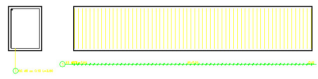
In the following procedure, you create drawings with different scales for the document shown below (cross section of an RC beam with a stirrup and view of a beam with stirrup distribution along the beam length).
Create views using the same method described in View scale definition.
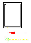
To change scale of one of the views (the scale of the view named Cross section view will be changed):
- Highlight the cross section view (from the context menu, right-click the Show view command or double-click on Cross section view) in the Object Inspector dialog.
- In the lower part of the Object Inspector dialog, define appropriate scale for a given view. All the descriptions included in the cross section view will be modified.
To add the created views to the printout:
- Click the printout layout tab (e.g. layout1 which is by standard provided in the AutoCAD® program).
- Choose the printout size (e.g. A2 paper size).
- Select the previously created view (e.g. Cross section view) in the Object Inspector dialog.
- In the context menu, right-click the Add to current Printout option.
- Position the view on the printout.
Using the same method, create a second view (Longitudinal view). The printout now included a beam cross section and a beam longitudinal section with transversal reinforcement.