Learn how to modify the display to show the stories by color and how to create a new analysis type for linear static analysis.
- Navigate to the Tutorials folder, and then open the project Structure-Seismic.rtd. This is similar to the project you worked on in the previous tutorial, but additional loads have already been added.
Note: The Tutorial files are located in C:\ProgramData\Autodesk\Examples\Tutorials.
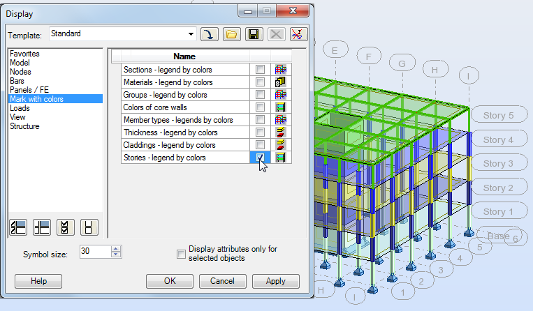
- To help display the modifications to the various stories of the structure, right-click and select Display.
- In the Display dialog box, select Mark with colors and then select Stories – legend by colors and click OK. Each of the stories displays a different color as shown below.
- In the Standard toolbar, click
 (Analysis Parameters). A variety of loads have already been applied to this model as shown below. You will now add a linear elastic static analysis type.
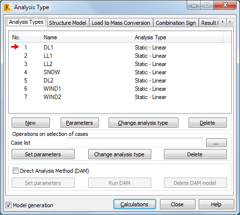
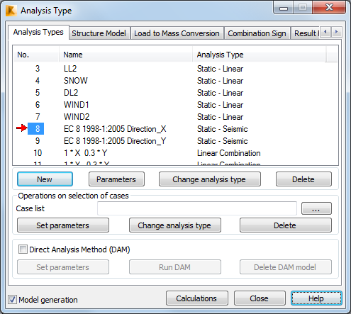
- In the Analysis Type dialog box, click New.
- In the New Case Definition dialog box, select Seismic (Equivalent Lateral Force Method) and click OK
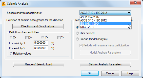
- In the Seismic Analysis dialog box, expand the list of codes in the upper left corner as shown below. Select EN 1998-1:2004.
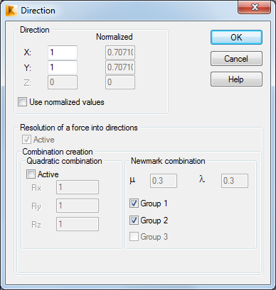
Note: Depending on the directions and eccentricities definitions, the series of static seismic load cases are generated. XY components of direction vectors are understood as additional multipliers for the calculated horizontal forces in each direction. - Continuing to work in the Seismic Analysis dialog box, click Directions and Combinations. For this project, set the Newmark combination to Group 1 and Group2 as shown below and click OK.
- In the Seismic Analysis dialog box, click Range of Seismic Load.
- In this dialog box, you can limit the levels on which the seismic load is distributed and define the structure height for the fundamental period calculation. The top and bottom stories can be defined automatically or manually. In this case we are leaving the stories set to Automatic. Click OK to close the dialog box.
- In the Seismic Analysis dialog box, in the Method of defining values of fundamental periods area, select Precise (modal analysis) as shown below.
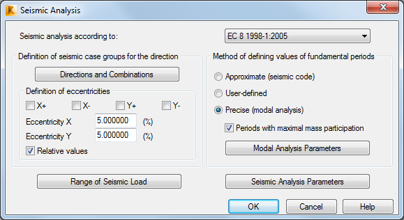
Note: The fundamental period methods include Approximate (where values are calculated according to formulas defined by code), User-defined (where values are added manually by the user), and Precise (which generates an additional modal case preceding seismic cases). - Click Modal Analysis Parameters so that you can review the settings in the Modal Analysis Parameters dialog box and click Cancel.
- In the Seismic Analysis dialog box, select the Approximate (seismic code) method and click Seismic Analysis Parameters.
Note: Parameters of the seismic simplified analysis depend on the seismic code.
- In the Parameters dialog box, next to Direction X, expand the drop-down list, and select RC frame. Repeat this for Direction Y as shown below.
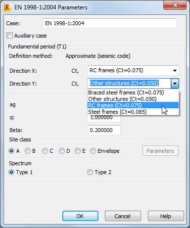
- Click OK to close the Parameter and Seismic Analysis dialog boxes to finish the creation of the new Seismic loads.
- In the Analysis Type dialog box, the two Load cases for the X and Y directions and the four combinations generated from them are displayed as shown below.
- Save the project.