Learn how to display the seismic loads graphically, in a table, and using the Calculation notes.
- In the Analysis type dialog box, click Calculations.
The calculations might take some time.Note: Acting forces for the load cases are generated during the structural analysis calculations.
- When the Analysis is complete, close the Analysis Type dialog box.
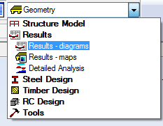
- In the Layout drop-down list, select Results and then select Results – diagrams as shown below.
- To display the loads more clearly, in the View Status Bar, turn off
 (Section Shapes).
 - Right-click and select Display.
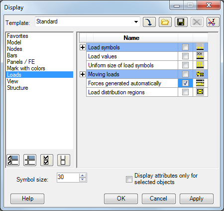
- In the Display dialog box, select Loads, and then select Forces generated automatically as shown below. Click OK.
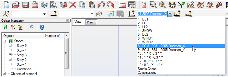
- The loads that display are the default DL1 loads. To display the seismic load, expand the Load Cases drop-down list and select E8:1-2005 Direction X as shown below.
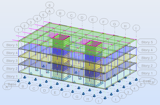
The forces display as shown below.
- To see information in table form, right-click and select Tables…
- In the Tables Data and Results dialog box select Loads, select Full table, and then click OK.
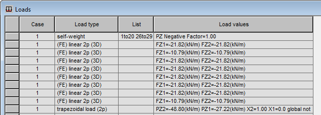
- In the Loads table click the Values tab.
- Right-click on the table and select Table Columns… as shown below.
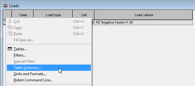
- In the Loads dialog box select Display loads automatically generated in the program and click OK.
- The loads now display as shown in part below.
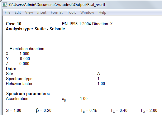
- Defined parameters and intermediate results of the Seismic Analysis may also be inspected in a Calculation Report. In the Menu Bar, click .
- Scroll down in the window to display the information copied to the report, such as this shown below.
- Once you have finished reviewing all of the information, save and close the project.
Click here to go to the Summary.