Learn how to open the Results layout and view the graphical information (diagrams) about the structure, including the impact of forces, stresses, and reactions. You also learn how to modify the Preferences of the diagrams.
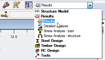
- In the Standard toolbar, expand the Layouts drop-down menu and select Results and then select Results again as shown below.
- The Results layout opens the Diagrams dialog box and a table of Reactions as shown below.
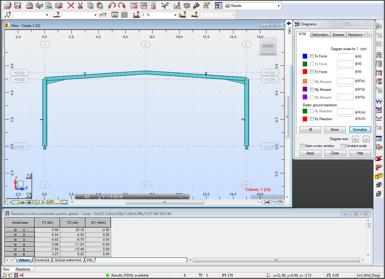
- In the Selection toolbar, select the type of case that you want to display. Verify that 1:G (the case that was created earlier) is selected.
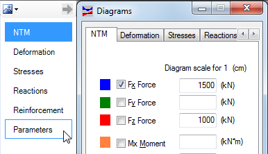
- In the Diagrams dialog box, you can specify the information that you want to display, including the internal forces (NTM), deformation, stresses, reactions, and reinforcement.
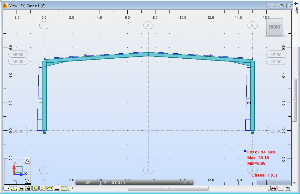
- In the NTM tab, select Fx Force and click Apply. The view displays the forces as shown below.
Note: If you want to modify the size of the diagram components, click the + and – buttons at the bottom of the dialog box as shown below. By default, the diagrams remain at a constant scale when you select different cases. You can also open a new window.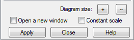
- Click the + button twice and then click Apply to increase the size of the forces.
- In the Selection toolbar, change Select Cases to display a different load case diagram.
- You can check other cases and then return to 1:G for the next steps.
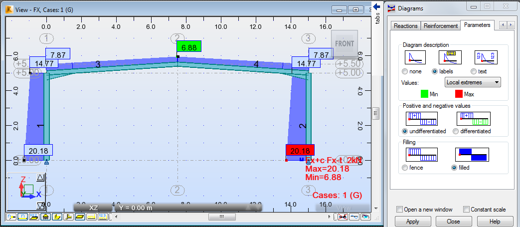
- The Parameters tab includes settings for the views. In the Diagrams dialog box, hover the cursor over the arrow near the title to expand the tabs on the side and then select Parameters as shown below.
Note: Using the side tabs is helpful when you are moving from the beginning to the end of the list without having to scroll through the tabs. - In the Parameters tab, set the Diagram description to labels and the Filling to filled and then click Apply. The view changes to match these parameters as shown below.
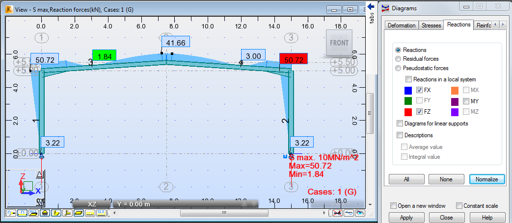
- Multiple charts can be applied to a view. Open the Stresses tab, select Maximum – S max and click Apply. The forces selected earlier and the stresses display.
- In the NTM tab, clear FX Force.
- In the Reactions tab, select FX and FZ and click Apply. The new combined diagram displays as shown below.
- If you have time you can display the other combinations.
- Save the project.