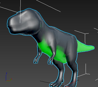
Stingray networks use "swizzling" to allow individual components of XYZ to take on the value of any of the RGB components.
By default, RGB values correspond to XYZ values: X matches R, Y matches G, and Z matches B. However, you can specify a float3 "swizzle" string of xxx or rrr—that is, the red channel is used for all of the three float values of the float3. You can also specify rgg or xyy, where the red channel is used for the first float value and the green is used for the second and third values.
You can create different shader effects by customizing the different channel inputs to the Standard Base node, such as Base Color or Opacity.
Setting component swizzle values:
- In the ShaderFX editor for your Stingray shader, click the attribute that you want to adjust on the Standard Base node; for example, Base Color.
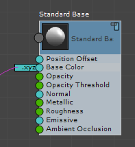 Note: Unlike ShaderFX nodes, the properties displayed for a Stingray node can change depending on which node attribute you click. They can also change depending on which node is providing the input to that attribute.
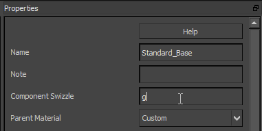
 - On the Properties panel, enter a Component Swizzle string that specifies the channels you want to input to this attribute.
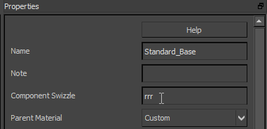
If the Component Swizzle field is empty, the default values are used (that is, rgb for xyz).

Left: Default values: rgb = xyz
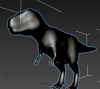
Right: Component Swizzle = rrr
Example: Connect the the vertex color green channel to Ambient Occlusion:
- Add an Input
 Material Variable node to the graph. Change its Type to Vector3 and its name to Color, and wire it to the Standard Base node's Base Color input.
 Your color map will provide the base color for your model.
- On the Material Editor, assign the Color a dark value.
- Connect the RGBA output of Vertex Color node to the Ambient Occlusion input of the Standard Base node.
The float3 output is converted to float automatically and the r channel is used by default.
- Click the Ambient Occlusion attribute on the Standard Base node. On the Properties panel, enter g in the Component Swizzle attribute.
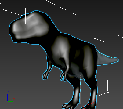
Ambient occlusion values now appear on those portions of the model with green vertices.
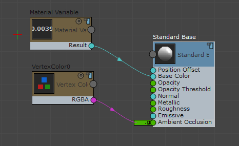
Graph for Vertex Color control of Ambient Occlusion
Note: You could now use the r and b channels of the Vertex Color node to control other inputs; for example, r for Metallic and b for Roughness.
This procedure continues from the previous one.
