The Point Cloud object lets you create precise, three-dimensional models from real-world references by importing large datasets captured from reality as point clouds: sets of data points in the form of 3D objects. 3D modelers can view point clouds in true color in the viewports, interactively adjust the extent of the cloud displayed, and create new geometry in context by snapping to point-cloud vertices. Support for the RCP and RCS file formats enables you to take advantage of a connected reality-capture workflow with other Autodesk solutions: Autodesk® ReCap™ Studio, AutoCAD®, Autodesk® Revit®, and Autodesk® Inventor® software.
-
 Create panel >
  (Geometry) > Point Cloud Objects > Object Type rollout > PointCloud
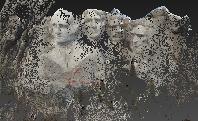
Point-cloud objects are made up of closely packed, self-illuminated individual points. Each point has its own color, so one way to think of a point cloud is as a 3D bitmap. Point clouds do not contain any other type of geometry such as edges or faces, so they do not change appearance with different viewport rendering modes, or respond to scene lighting by default. Also, the Point Cloud object currently does not support conversion of point clouds into geometry. You can, however, snap to points, which makes it relatively easy to create geometry that conforms to the shape of the point cloud.
The main benefit of using the Point Cloud object is that you can incorporate complex, realistic 3D objects in your scenes without having to model them explicitly. The consequent drawback is that these objects are not directly editable using traditional 3D-modeling techniques.
Point Cloud Objects, Materials, and Lighting
When you add a point-cloud object to the scene, 3ds Max automatically applies an Autodesk Point Cloud material to it. In general you don't need to adjust this material, but if necessary it provides controls for color intensity, ambient occlusion, and shadow reception.
Because of the nature of the default material, point-cloud objects do not, by default, respond to scene lighting. That is, they appear with the lighting under which they were originally captured. To enable the object to respond to scene lighting, follow this procedure:
To enable point-cloud objects to respond to scene lighting:
- Apply an Arch & Design material to the object.
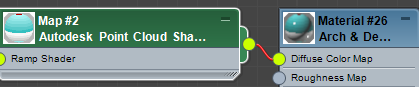
- Apply an Autodesk Point Cloud shader to the Arch & Design material's Diffuse Color Map input.
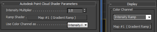
- Open the Autodesk Point Cloud shader settings in the Material Editor.
- If a shader is applied to the point-cloud object's color channel, such as when using the Elevation Ramp option, copy the shader from the Map button on the point-cloud object's Display rollout (command panel) to the Ramp Shader button on the Point Cloud Shader Parameters rollout in the Material Editor as an instance. An easy way to do this is simply by dragging and dropping from the command panel to the Material Editor. When the dialog opens querying Instance or Copy, make sure Instance is chosen and click OK.
The following illustration shows the result of doing this: Map #1 (Gradient Ramp) has been copied from the Display rollout on the right to the Ramp Shader parameter on the left.
- Also on the Point Cloud Shader Parameters rollout, set the Use Color Channel As parameter (drop-down list) to the active option on the command panel Display rollout; for instance, Intensity Ramp.
This gives the point-cloud object a look similar to that obtained with the default material, with the added benefit of enabling the object to respond to scene lighting. Note, however, that any shadows incorporated in the original capture remain.
Procedures
To create a point-cloud object:
- Go to the Create panel, click the Geometry button, and from the drop-down list, choose Point Cloud Objects. Then, on the Object Type rollout, click PointCloud.
- Click in the viewport to create a point-cloud object.
- On the command panel, find the Point Cloud Source rollout and click the Load Point Cloud button.
This opens a file dialog.
- Find an RCS or RCP point cloud file and open it. Tip: You can create custom point cloud files and 3D mesh objects from a series of photos with the free Autodesk RECAP Photo online app: http://recap.autodesk.com/.
3ds Max displays the point cloud data in the viewport. If it's not readily apparent, you can try a couple of things:
- The point cloud might be outside the viewport, so in the viewport navigation controls (bottom-right of the interface), click
 Zoom Extents All Selected.
 This changes the magnification and viewpoint in all viewports to closely fit the point cloud data.
- Also, you might need to increase the point size: On the Display rollout, in the Point Display group, drag the spinner to the right of the As Pixel setting upward until the points resolve into a visible object.
- The point cloud might be outside the viewport, so in the viewport navigation controls (bottom-right of the interface), click
- Now that the point-cloud object is present in your scene, you can transform it like any other object. You can also change the material and cause other objects in the scene to cast shadows on it. The most important point to remember is that you must use the NVIDIA mental ray renderer to render point-cloud objects.
To use the Limit Box to hide parts of the point-cloud object:
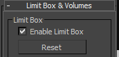
- Select a point-cloud object and make sure the Enable Limit Box switch on the Limit Box & Volumes rollout is on.
When the limit box is enabled, only portions of the point cloud inside its volume are visible.
- On the Modify panel, expand the modifier stack and click the Limit Box item to highlight it.
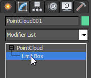
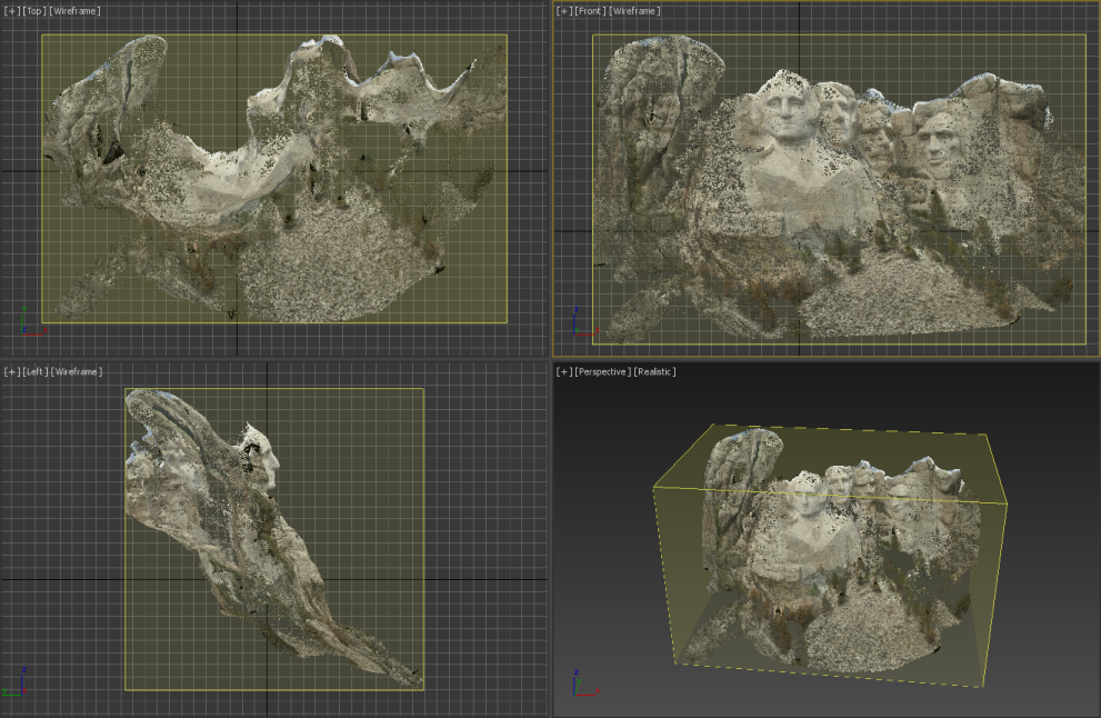
This causes the limit box to appear in the viewports as a yellow, translucent bounding box encompassing the point-cloud object.
- Use a transform tool to edit the box as follows:
 Select and Move By default, you can select one side of the bounding box at a time. To skew the box, drag one side within its own plane. To resize the box in one dimension, drag one side along its in-out axis.
 To select the entire box, first select one side, then Ctrl+click to select another side. You can now move the box in any direction. Only portions of the point-cloud object that remain inside the box are visible.
 Select and Rotate Rotating any side of the Limit Box rotates the entire box.
  Select and Scale Scaling any side of the Limit Box along a single axis resizes the box non-uniformly along that axis. Scaling a plane handle or the center of the Scale gizmo resizes the entire box uniformly.
In some cases, you might want to prevent parts of a point-cloud object from appearing in the scene. Examples of this include hiding undesirable artifacts of the reality-capture process, or elements that are irrelevant to the current project. The Limit Box sub-object level provides a box-shaped volume that allows only portions of the point cloud inside (or outside) it to be visible. You can move the entire volume or a single side. You can also rotate and scale it.
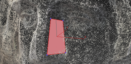
To create geometry from a point-cloud object:
- Follow the first procedure, preceding, to create a point-cloud object.
- Also create any geometry primitive, such as Box, and convert it to editable poly format.
- Go to the Polygon sub-object level of the editable poly object and, on the Edit Geometry rollout, turn on Create.
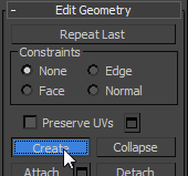
The Create tool enables creating polygons one at a time by clicking their corners.
- On the main toolbar, click
 to turn on snapping, then right-click the same button to open the Grid And Snap Settings dialog.
 By default, the dialog opens to the Snaps panel with the Standard category active and the Grid Points option enabled.

- Turn off Grid Points, then click Standard and choose Point Cloud Objects from the drop-down list.
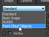
- In the Point Cloud Objects category, turn on the single option: Point Cloud Vertex. Close the dialog.
Now it simply remains to create polygons on the surface of the point-cloud object.
- Position the mouse cursor over the point-cloud object at a surface corner and click.
- Move the mouse to an adjacent corner and click again. Repeat until the polygon shape is fully defined, then right-click to complete the polygon.
The polygon appears and the Create tool remains active.
- Continue creating polygons, then exit the Create tool.
You can use other polygon-editing tools such as vertex welding to combine the polygons into a single object. You might also want to delete the original object's geometry from step 2, at any sub-object level, leaving just the newly created polygons.
You can use a point-cloud object as a template for creating standard geometry such as editable poly objects. You create the polygon mesh one point at a time, snapping to vertices in the point-cloud object. You can then use standard modeling techniques such as extrusion and sub-object transforms to customize the object.
Interface
Point Cloud Source rollout
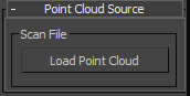
- Scan File
- Click the Load Point Cloud button, then use the file dialog that opens to navigate to and open a point-cloud file (RCS or RCP). Thereafter the file name appears on the button and the point-cloud data appears in the viewports.
Display rollout
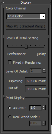
- Color Channel
- The method of coloring the point-cloud data in the viewports and in rendered output. Choose one of the following from the drop-down list:
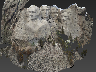
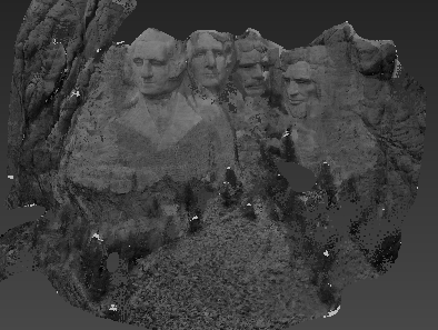
- True Color Displays the original colors in the point-cloud file. Typically these colors are relatively faithful to those in the digitized scene. This is the default Color Channel setting.
- Elevation Ramp Applies a vertical color gradient derived from a Gradient Ramp map to the point-cloud object. The leftmost point in the gradient corresponds to the bottom of the point-cloud object while the rightmost gradient point corresponds to the top of the point-cloud object.
To change the default grayscale gradient map, click the (Gradient Ramp) button below the drop-down list. This opens the Material/Map Browser, from which you can apply a different map, or choose the current map (under Scene Materials) to edit. You can apply any map, but only the Gradient Ramp map is meaningful in this context.
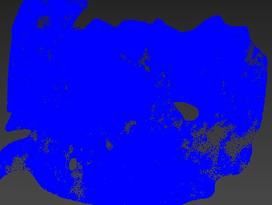
Tip: The Elevation Ramp option can be useful for visualizing relative heights of a scanned area for analysis. For example, you can apply a gradient to a terrain to see where water will drain (highest areas) and where it will accumulate (lowest areas). Using a highly differentiated gradient makes it easier to see these areas from the top.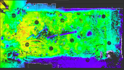
Top view of a point cloud of a terrain, with elevation ramp showing the relative heights of different areas
Red is the lowest elevation and blue is the highest.
- Intensity Ramp Applies a texture derived from a Gradient Ramp map to the point-cloud object based on luminance values in the point cloud's original coloring. The leftmost point in the gradient corresponds to the darkest areas of the point-cloud object's original coloring while the rightmost gradient point corresponds to the brightest areas in the point-cloud object.
To change the default grayscale gradient map, click the (Gradient Ramp) button below the drop-down list. This opens the Material/Map Browser, where you can apply a different map, or choose the current map (under Scene Materials) to edit. You can apply any map, but only the Gradient Ramp map is meaningful in this context.
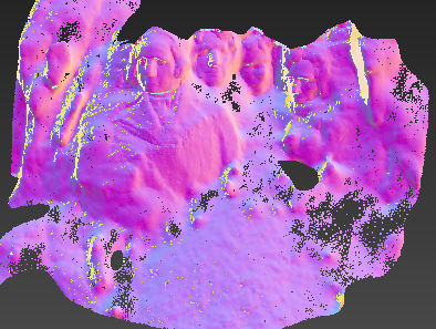
- Normal Ramp Applies coloring similar to that of a Normal Bump map to the point-cloud object. The coloring of each point depends on its normal direction.
- Single Color Applies a solid color to the point-cloud object. To change the color, click the color swatch below the drop-down list.
- True Color Displays the original colors in the point-cloud file. Typically these colors are relatively faithful to those in the digitized scene. This is the default Color Channel setting.
Level Of Detail Setting group
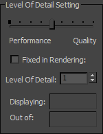
- Performance/Quality slider
- Controls the number of visible points in the cloud in the viewports. When Fixed In Rendering (see following) is off, this setting also affects the rendered output. To reduce the number of visible points and improve performance, move the slider toward the left (Performance) end of the scale. To increase the number of visible points, move the slider toward the right (Quality) end of the scale. For better-looking results at the potential cost of performance, use the right side of the scale.
The number of points currently visible and the total number of points in the object appear in the read-only fields at the bottom of the Level Of Detail Setting group: Displaying and Out Of, respectively.
Note: The available range of points depends on the viewpoint distance from the point-cloud object. Typically a wider range is available at greater distances, and moving the viewpoint closer reduces the range at the both ends. So the number of visible points at the Performance setting is lower when the viewpoint is relatively distant from the object, and higher when closer to the object.The following illustration shows the results of using the extreme ends of the scale at different distances with a point-cloud object containing about 444,000 points.
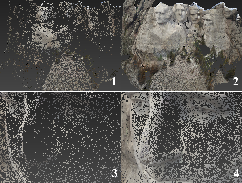
Point cloud object viewed from far away (top) and close up (bottom):
1: Performance (13,600 points visible)
2: Quality (444,000 points visible)
3: Performance (161,000 points visible)
4: Quality (384,800 points visible)
- Fixed In Rendering
- When on, the Level Of Detail setting (see following) determines the visible number of points at render time. In this case, the Performance/Quality slider (see preceding) has no effect on rendered output.
- Level Of Detail
- Determines the number of points in the object visible in rendered output when Fixed In Rendering (see preceding) is on. The higher the value, the more points in the object are rendered. Range=1 to 100. Default=1.
- Point Display
- Choose how points in the cloud are displayed:
- As Pixel Each visible point in the cloud is displayed as a single point of color, or pixel. The numeric setting serves as a multiplier for the pixel size. The greater the multiplier value, the larger the point.
- Real-World Scale Shows and enables you to set the displayed point size in terms of the current Display Unit Scale setting.
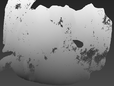
The following illustration depicts a point-cloud model at the lowest Level Of Detail setting (Performance) with three different As Pixel values. Note that the lower As Pixel values permit seeing "through" the closest surface to the underlying surfaces.
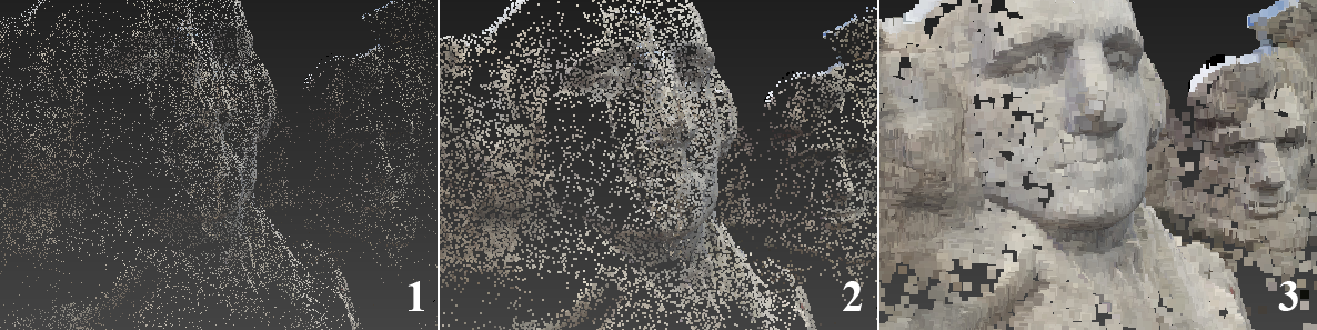
1: As Pixel = 0.5
2: As Pixel = 1.0
3: As Pixel = 4.0
Tip: One way to get good performance with a solid-looking object is to use a relatively large Point Display setting with a low Level Of Detail setting.
Limit Box & Volumes rollout
The Point Cloud object provides two ways of hiding parts of the point-cloud data: Limit Box and Display Volumes. If you want to hide all but a section of the data that fits inside or outside a single box-shaped volume, the Limit Box method is easier because it doesn't require external objects. But if you want to hide multiple, non-contiguous parts of the data, it might be necessary to use the Display Volume feature with the supported geometry primitives: Box, Sphere, and Plane.
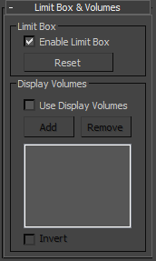
- Limit Box
- When Enable Limit Box is on, you can restrict visibility of the point-cloud object to the volume within the Limit Box sub-object. For details, see this procedure.
- Reset
- Restores the Limit Box to its default size and position.
- Display Volumes
- When Use Display Volumes is on, you can use other objects in the scene to specify parts of the point-cloud object to render or prevent from rendering. By default, only parts of the point-cloud inside the display-volume objects are visible. To reverse this, turn on Invert (see following).
This tool supports only the Box primitive, the Sphere primitive, and the Plane primitive. With the Plane primitive, points qualify as being inside the display volume if they're behind the plane; that is, on the non-rendering side.
Use the Add and Remove controls to manage the list of display-volume objects. To stop adding, right-click in a viewport or click Add again.
Tip: For best visibility of the point-cloud object, hide the display-volume objects after adding them.
1: Point-cloud object with box primitive placed as display volume
2: Box used as display volume with Invert off (the default setting), then hidden. Only points inside the box are visible.
3: Box used as display volume with Invert on, then hidden. Only points outside the box are visible.
- Invert
- When Invert is off (the default), only points inside the display-volume objects are visible. To reverse this, thus displaying only points outside the display-volume objects, turn on Invert.