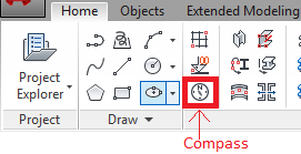
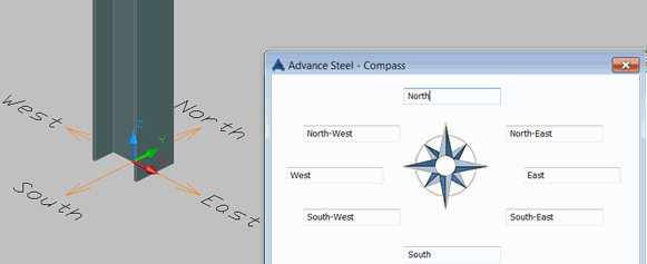
To use the orientation marks, it is necessary to create the compass in the model.
The compass is created in the XY plane corresponding to the current position of the UCS. The compass can be moved using the grip points. You can define its orientation in its properties dialog box. Only one compass can be added to a model.
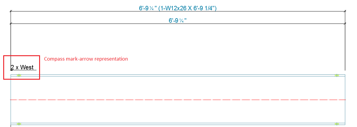
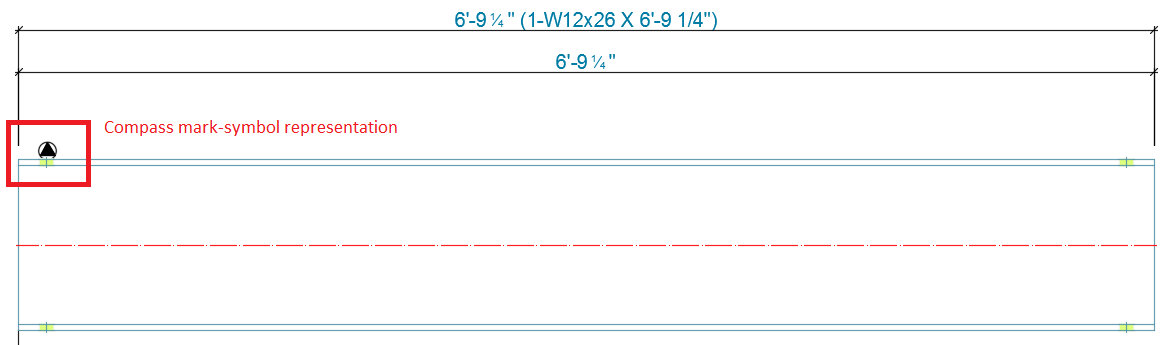
Compass marks for main part / single part details
For main part / single part details, you can activate the compass from the advance view settings or by configuring the drawing style.
To activate this feature using drawing style, follow these steps:
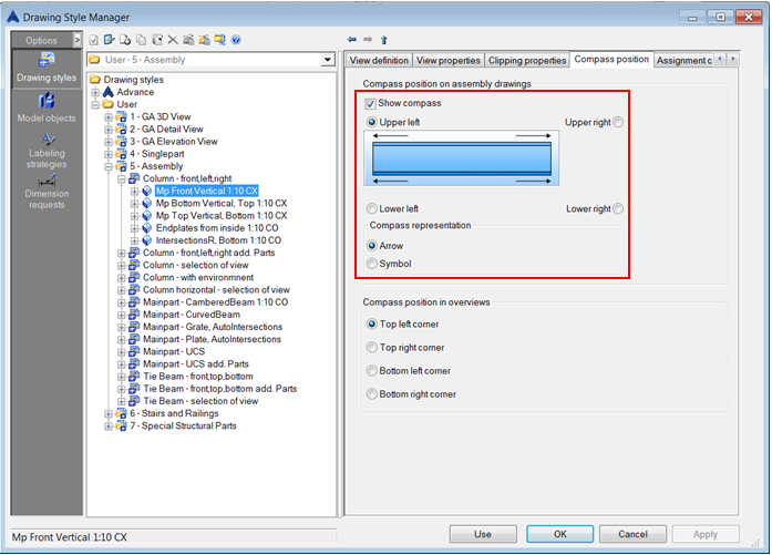
- Open the Drawing Style Manager
- Select the desired drawing style and expand it
- Select the desired view of the drawing style
- On the right side of the dialog box, open the Compass position tab
- Activate the option Show compass
- Define compass position (the four corners)
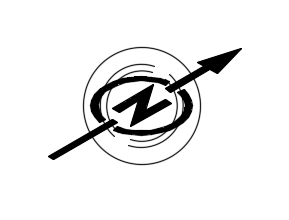
- Choose the Compass representation type: Arrow or Symbol
- Use the Apply button
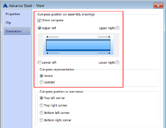
To activate this feature from the Advance view settings in detail drawing, follow these steps:
- Open the detail drawing
- Right click on a detail and select Advance Properties
- Select the Orientation tab
- Activate the option Show compass
- Define compass position (the four corners)
- Choose the Compass representation type: Arrow or Symbol
- Use the OK button
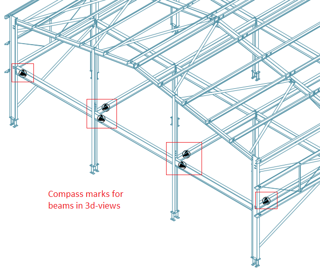
Compass marks on GA/overview drawings
The compass marks on GA/overview drawings will be created only for the assemblies(main parts) that were already detailed with the compass mark feature activated.
For GA/overview drawings, you can activate the compass marks by configuring the drawing style(DS).
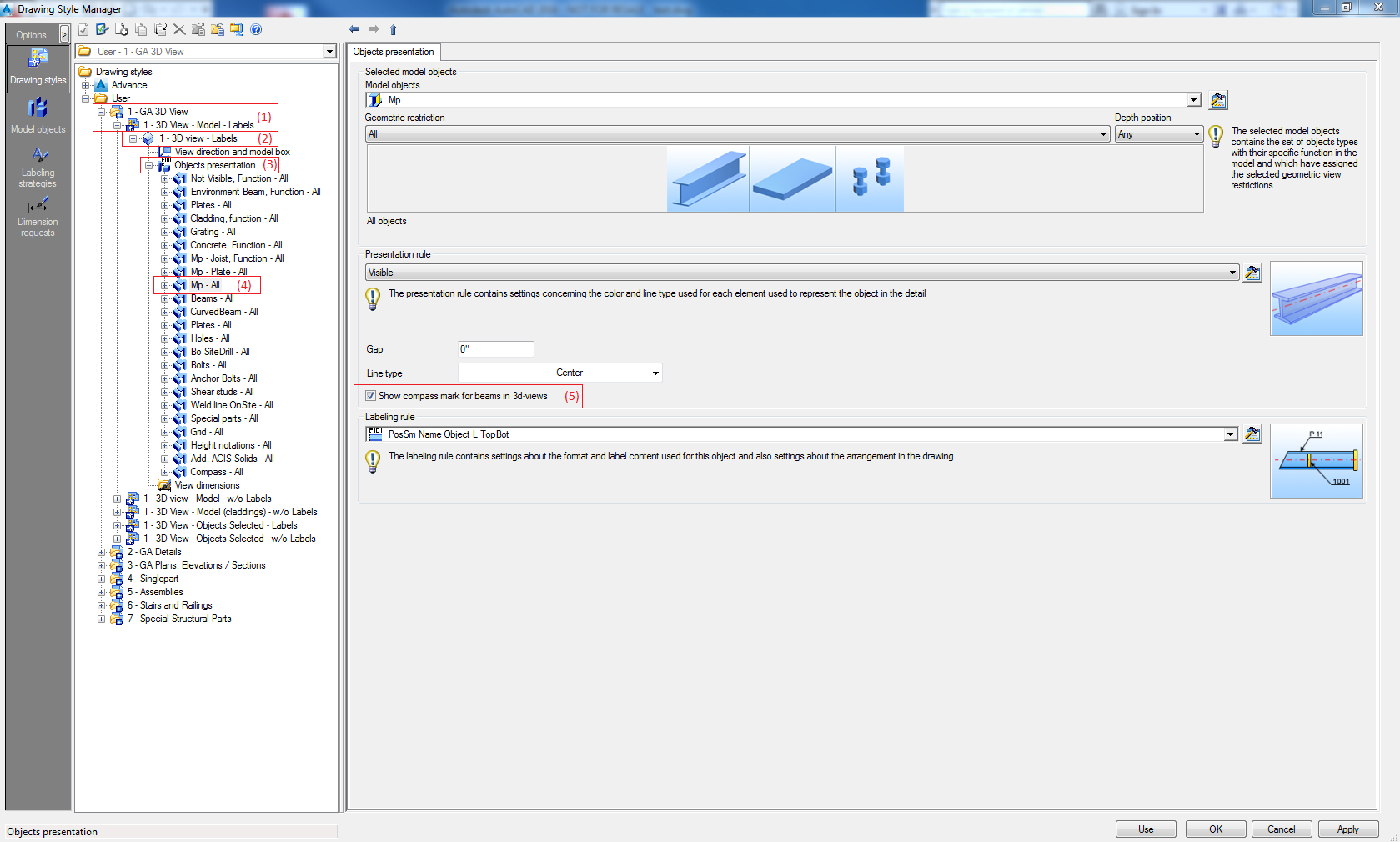
To get compass marks on GA/overview drawings, follow these steps:
- Open the Drawing Style Manager
- Select the desired Drawing Style(1)
- Select the desired view of the DS(2)
- Select the Object presentation category and expand it(3)
- Select the objects on which you want to get the compass mark(4)
- In the right side of the dialog box (Object presentation tab), activate the option Show the compass mark for beams in 3D-views(5)
- Use the Apply button
Displaying the compass in an overview drawing
For GA/overview drawings, you can display the compass by configuring the drawing style.
Most of the drawing styles for GA/overview drawings are configured to display the compass, if not, follow these steps:
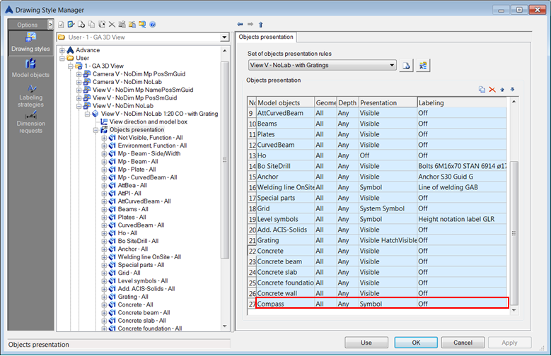
- Open Drawing Style Manager
- Select the desired Drawing Style
- Select the desired view of the Drawing Style and expand it
- Select Object presentation
- In the right side of the dialog box(Object presentation tab), add a new presentation
- In the Selected model objects, click Rename and enter the name Compass for the new presentation
- In the model object list, select Compass
- In the model role list, select All model
- In the Filter list, select None
- Define the Presentation rule as Symbol
- Use the Apply button
- Select the desired view of the DS
- On the right side of the dialog box, open the Compass position tab
- Using the "Compass position in overviews" options, you can define the corner where the symbol is placed
- Use the Apply button