Creates a three-sided or four-sided surface in 3D space.
Access Methods
 Menu: Draw
  3D Modeling Meshes 3D Face
Summary
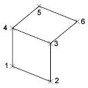
After entering the last two points for a 3D face, the command repeats automatically using the these two points as the first two points of the next 3D face. For example:
List of Prompts
The following prompts are displayed.
Specify first point or [Invisible]: Specify a point (1) or enter i
- First Point
-
Defines the start point for the 3D surface. After entering the first point, enter the remaining points in a natural clockwise or counterclockwise order to create a normal 3D face. If you locate all four points on the same plane, a planar face is created that is similar to a region object. When you shade or render the object, planar faces are filled.
- Invisible
-
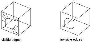
Controls which edges of a 3D face are visible, allowing for accurate modeling of objects with holes. Entering i or invisible before the first point of an edge makes the edge invisible.
The invisible specification must precede any object snap modes, XYZ filters, or coordinate input for that edge. You can create a 3D face in which all edges are invisible. Such a face is a phantom; it does not appear in wireframe presentations but can hide material in line drawings. 3D faces do appear in shaded renderings.
You can combine 3D faces to model complex 3D surfaces.
Specify second point or [Invisible]: Specify a point (2) or enter i
Specify third point or [Invisible] <exit>: Specify a point (3), enter i, or press Enter
Specify fourth point or [Invisible] <create three-sided face>: Specify a point (4), enter i, or press Enter
The Third Point and Fourth Point prompts are repeated until you press Enter. Specify points 5 and 6 at these repeating prompts. When you finish entering points, press Enter.