Allows you to control the geometric constraints, dimensional constraints, and autoconstrain settings.
List of Options
The following options are displayed.
The Constraint Settings dialog box includes the following:
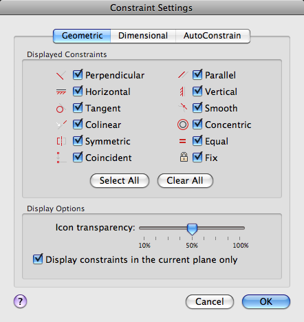
Geometric Tab
Controls the display of constraint types on constraint bars.
- Infer Geometric Constraints
-
Infers geometric constraints when creating and editing geometry.
- Displayed Constraints
-
Controls the display of constraint bars or constraint point markers for objects in the drawing editor.
For example, you can hide the display of constraint bars for Horizontal and Vertical constraints.
- Select All
-
Selects the geometric constraint types.
- Clear All
-
Clears the selected geometric constraint types.
- Display Constraints in the Current Plane
-
Displays constraint bars for geometrically constrained objects only on the current plane.
- Icon Transparency
-
Sets the transparency level of constraint bars in a drawing.
- Show Constraint Bars After Applying Constraints to Selected Objects
-
Displays relevant constraint bars after you apply a constraint manually or when you use the AUTOCONSTRAIN command.
- Temporarily Display Constraint Bars When Objects Are Selected
-
Temporarily displays the constraint bars of the selected objects.
Dimensional Tab
Sets preferences in behavior when displaying dimensional constraints.
- Dimensional Constraint Format
-
Sets the display of the dimensional name format and lock icon.
- Dimension Name Format
-
Specifies the format for the text displayed when dimensional constraints are applied.
Set the name format to display: Name, Value, or Name and Expression.
For example: Width=Length/2
- Show Lock Icon for Annotational Constraints
-
Displays a lock icon against an object that has an annotational constraint applied (DIMCONSTRAINTICON system variable).
- Show Hidden Dynamic Constraints for Selected Objects
-
Displays dynamic constraints that have been set to hide when selected.
Autoconstrain Tab
Controls the constraints that are applied to a selection set, and the order in which they are applied when using the AUTOCONSTRAIN command.
The following conditions are checked before multiple geometric constraints are applied:
- Are the objects perpendicular or tangential to each other within the tolerances specified in the AutoConstrain tab?
- Do they also intersect within the specified tolerances?
If the first condition is met, then tangent and perpendicular constraints are always applied if the check boxes are cleared.
If you select the additional check boxes, then the distance tolerance is considered for intersecting objects. If the objects do not intersect but the nearest distance between them is within the distance tolerance specified, then the constraint will be applied even if the check boxed are selected.
- Autoconstrain Headings
-
- Applied — Controls the constraints that are applied when applying constraints to multiple objects.
- Constraint Type — Controls the type of constraint applied to objects.
- Tolerances
-
Sets the acceptable tolerance values to determine whether a constraint can be applied.
- Distance — Distance tolerance are applied to coincident, concentric, tangent, and collinear constraints.
- Angle — Angular tolerance are applied to horizontal, vertical, parallel, perpendicular, tangent, and collinear constraints.
- Tangent Objects Must Share an Intersection Point
-
Specifies that two curves must share a common point (as specified within the distance tolerance) for the tangent constraint to be applied.
- Perpendicular Objects Must Share an Intersection Point
-
Specifies that lines must intersect or the endpoint of one line must be coincident with the other line or endpoint of the line as specified within the distance tolerance.