The following procedure describes how to import an underlay in ESTmep using a .PDF file as the file type being imported. The procedure for importing an underlay in CAMduct is similar, although PDF is not a file type that is supported in CAMduct for importing as an underlay.
To import an underlay in ESTmep:
- Before importing an underlay, ensure that the following features are enabled from the top menu bar:
-
In ESTmep and CAMduct, click View
 Use Services to enable compatibility with Design Line.
-
In ESTmep, click View
CAD Mode to enable CAD mode.
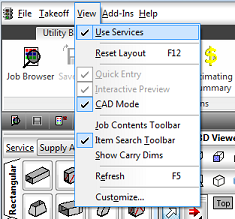
The 3D Viewer requires these to be enabled in order to best utilize the import and trace features.
-
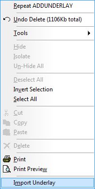
- In the 3D Viewer, right-click on the background and select Import Underlay.
-
On the Import Underlay dialog, in the of Type drop-down near the bottom of the dialog, select a file type to display just the files of the selected type in that location. For this example, select PDF Files (*.PDF), as shown below.
Note: In ESTmep, you can import many common file types as an underlay, including PDF, DWG, DXF and DWF. Note that CAMduct does not support importing PDF or DWG as an underlay.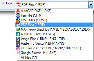
- At the top of the Import Underlay dialog, in the Look In field, click on the drop-down arrow and browse to and select the folder containing the file that is to be imported as an underlay.
Note: Select just the folder, not the file itself. Also note that hovering the mouse cursor over a PDF file name displays the first page of the PDF in the preview pane.
- In the left pane, over the mouse cursor over the file name of the PDF file you want to import, but do not click on it. Simply hover the mouse cursor over the file name.
If you the PDF you selected contains multiple pages, you will need to select the page to import.
- With the desired PDF filename highlighted in the left pane, click the Pages drop-down list and select the page to import.
- Click Open.
As soon as you click Open, a Progress indicator dialog displays, showing the progress of loading the file into the preview. This may display for just a few seconds, depending on the size and speed of the import. When the preview loading is complete, page selected displays in the Select Layers dialog. The import is not yet complete.
-
On the Select Layers dialog, you can perform a variety of functions on the data being imported. For example, you can:
- Use 3D Viewer toolbar commands -- The preview window is immediately updated when changes are made using the following controls located on the 3D Viewer toolbar:
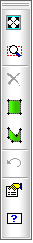
- Zoom to Fit
 : Displays the underlay in the maximum view size possible in the view window.
-
Zoom to Selected Region
 : Allows selection of a particular area on the underlay. Left clicking 2 points will zoom to the selected region.
-
Delete Layer: To delete a layer, select objects on the graphical view and click the Delete option
 when the desired layer(s) are selected. CTRL + Z to undo deletion.
-
Clip to Window
 and
Clip to Region
and
Clip to Region : These options allow selection of a particular area. Once activated from the toolbar, begin to draw a window or lined region around the layer objects to be isolated on the underlay. Right click to confirm and the objects outside the identified region will be removed.
- Undo: Click to undo and revert back to previous state.
-
Viewer Settings
 : Displays the Viewer Setting dialog which provides access to edit several commonly changed options; for example, the Colors tab
Background Color.
: Displays the Viewer Setting dialog which provides access to edit several commonly changed options; for example, the Colors tab
Background Color.
-
Command List
 : Displays all shortcut commands available which can be typed into the viewer, most of which are icons on the toolbar.
- You can also specify the following options:
-
Show: Clicking the lightbulb icon toggles the display of the layer. A yellow lightbulb icon
 displays the layer (Show). A dark lightbulb icon
 hides (does not display) the layer.
- Snaps: Toggles the display of snaps on all objects in the selected layer. If desired, you can use snapping tools to set the scale of the underlay as it is imported.
- Import/Export Name:The layer name assigned when the file was constructed.
- Color: Editable color of the layer, clicking the color square allows alternative selections to be assigned to the underlay layer.
- Style: Can apply a style to the layer if none existed or to override current style used in the file (Continuous, Dashed, Solid, Dotted etc.).
- Weight: Line weight defined for the layer, clicking the selection allows alternatives to be applied.
-
Show: Clicking the lightbulb icon toggles the display of the layer. A yellow lightbulb icon
- Invert selected items.
- Zoom to Fit
Tip: Certain file types do not require scaling. It is recommended as a best practice to verify the scale of an imported underlay. There are a few different methods that can be used to scale an imported underlay. For more information, see Set the Scale of an Imported Underlay.
- Use 3D Viewer toolbar commands -- The preview window is immediately updated when changes are made using the following controls located on the 3D Viewer toolbar:
- When you have finished making any adjustments to the underlay using the commands available, click OK on the Select Layers dialog to import the underlay.
When the import is complete, the imported model displays on the current Layout tab at the bottom of the 3D Viewer.
- If desired, you can change the name of the Layout tabs by right-clicking on the Layout tab name
Rename Layout.