The New Mill Tool dialog box lets you edit an individual tool and is divided into six tabs:
- General - Number, offsets, description etc.
- Cutter - The shape of the cutting part of the tool.
- Shaft - The shape of the non-cutting part of the tool.
- Holder - Selection of holder.
- Holder Geometry - Definition of holder shape.
- Feed & Speed - Parameters for cutting and non-cutting feedrates and spindle speed.
The preview on the right side of the dialog displays the shape of the tool and is automatically updated to reflect any changes you make.
General tab settings
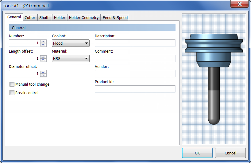
Number:
The number used to select the tool on the CNC machine.
Length offset:
The index of the tool length offset. This parameter is normally set when using tools with multiple tips indexed by length.
Diameter offset:
The index of the tool diameter offset.
Manual tool change
Enable to force a manual tool change on machines with an automatic tool changer.
Break control
Enable to check for tool breakage after use.
Coolant:
The type of coolant used with the tool.
Material:
The tool material.
Description:
A textual description of the tool. This description is included in the tool name shown throughout Inventor HSM.
Comment:
A text comment for the tool. The comment is typically included in the post-processed output.
Vendor:
The vendor of the tool. Use this to identify the specific tool used.
Product id:
The vendor's identifier (ID) for the tool. Use this to identify the specific tool used.
Cutter tab settings
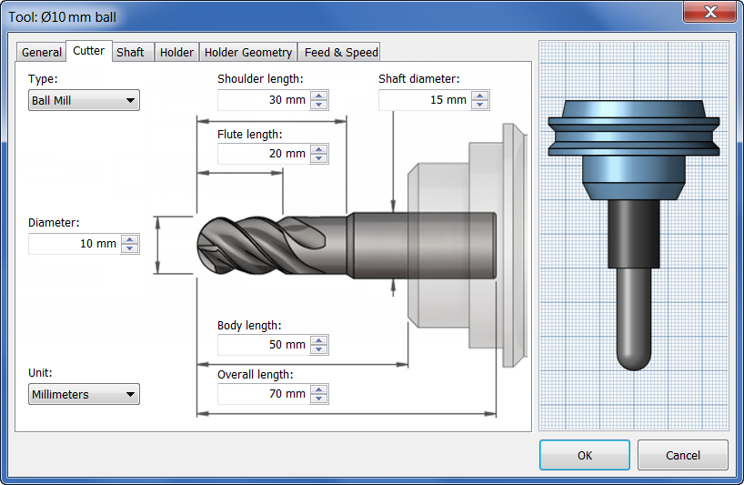
Type:
The type of the tool.
Diameter:
The diameter of the cutter.
Unit:
The tool unit (Millimeters or Inches).
Tip diameter:
The tip diameter of the cutter.
Corner radius:
The corner radius of the cutter.
Taper angle:
The taper angle.
Tip angle:
The angle of the tool tip. This angle is used to calculate the extra depth needed to break the tool through the material.
Flute length:
The tool flute length.
Shoulder length:
The tool shoulder length.
Body length:
The tool body length.
Overall length:
Specifies the entire length of the tool.
Shaft diameter:
The tool shaft/arbor diameter.
Thread pitch:
The pitch of the tap thread, specified as the vertical distance between the teeth of the tap.
Shaft tab settings
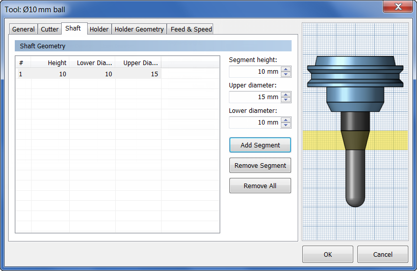
Segment height:
The height of the selected tool shaft segment.
Upper diameter:
The upper diameter of the selected tool shaft segment.
Lower diameter:
The lower diameter of the selected tool shaft segment.
Holder tab settings
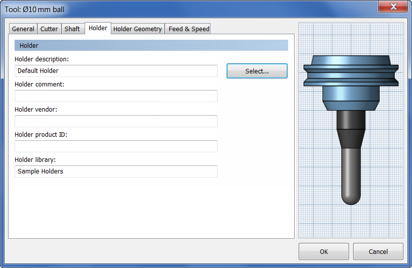
Holder description:
A textual description of the tool holder.
Holder comment:
A text comment for the tool holder.
Holder vendor:
The vendor of the tool holder.
Holder product ID:
The vendor's identifier (ID) for the tool holder.
Holder library:
The library where the tool holder is stored.
Holder Geometry tab settings
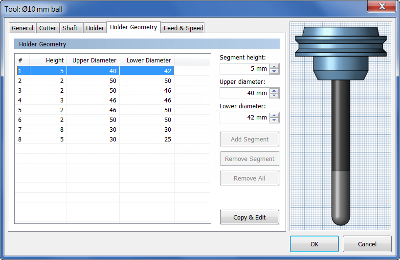
Segment height:
The height of the selected tool holder segment.
Upper diameter:
The upper diameter of the selected tool holder segment.
Lower diameter:
The lower diameter of the selected tool holder segment.
Feed & Speed tab settings
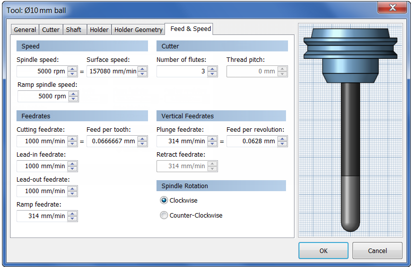
Speed group
Spindle speed:
The rotational speed of the spindle.
Surface speed:
The spindle speed expressed as the speed of the tool on the surface.
Ramp spindle speed:
The rotational speed of the spindle when performing ramp movements.
Cutter group
Number of flutes:
The number of cutting flutes on the tool.
Thread pitch:
The pitch of the tap thread, specified as the vertical distance between the teeth of the tap.
Feedrates group
Cutting feedrate:
Feed used in cutting moves.
Feed per tooth:
The cutting feedrate expressed as the feed per tooth.
Lead-in feedrate:
Feed used when leading in to a cutting move.
Lead-out feedrate:
Feed used when leading out from a cutting move.
Ramp feedrate:
Feed used when doing helical ramps into stock.
Vertical Feedrates group
Plunge feedrate:
Feed used when plunging into stock.
Feed per revolution:
The plunge feedrate expressed as the feed per revolution.
Retract feedrate:
Feed used when retracting and not using rapid (G0) moves.
Spindle Rotation group
Clockwise
This option is active by default. All tools (except left-handed taps) rotate clockwise (M3).
Counter-Clockwise
If selected, spindle rotation is reversed.