Render Loop Overrides

A render loop override is represented in the API as an MRenderOverride.
As the name implies a plug-in of this type overrides the entire rendering for a complete frame. Unlike older interfaces there are no fixed entry points to insert or remove specific render logic in the render loop. For example there is no such thing as a “pre” and “post” “pass” callback. Instead the intention is to provide the appropriate mix of building blocks and pipeline exposure to allow the plug-in to define arbitrarily complex pipeline logic.
An override is broken down into a set of operations. Predefined operations, which execute parts of the internal pipeline, as well as custom operations represent the base set of building blocks. Operations are designed to fully describe data inputs and outputs, and by default execute independently of each other. The main connection between operations is thus data. All operations render into a render target and data is explicitly passed between operations by sharing render targets.
The following is a set of basic operations available:
- Scene render: Draw renderable objects into a render target
- 2D quad render: render a 2d quad to a render target. Can take a render target as input.
- User defined operation: Custom rendering to a render target.
- Heads-up-display: Render a 2d HUD to a render target. Specific to 3d viewports.
- A present operation: Make a render target visible for interactive preview. Specific to 3d viewports.
As these operations are embedded into the rendering pipeline, a rendering state is provided to operations as necessary. This information is generally determined at the beginning of a frame and is implicitly set as default values for each operation. Overrides which are set per operation do not persist between operations.
- The set of renderable objects
- The output render targets.
- The camera and viewport parameters.
- The render state.
- The renderer preferences. It is not advisable to change render global state during a frame render.
Depending on the amount of customization, the interfaces are mostly draw API agnostic.
Unlike previous API implementations, sequence is specified by plug-in code and is not defined by the interface. The plug-in is therefore required to break down the desired render loop into a linear list of operations. A basic look at the API interface shows an example of the type of render loop that can be specified (left). The plug-in determines the appropriate ordering of operations. On the right is the basic multi-pass looping logic for old interfaces. Here, sequence is predefined based on the interface.
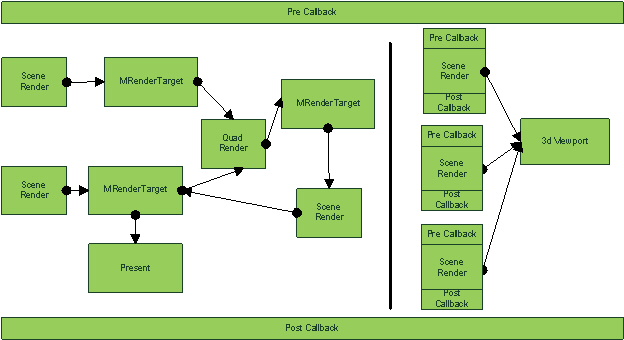
Figure 45: On the left, render targets serve as a means to pass context between operations as outputs and/or inputs. On the right, a series of scene render ‘passes’ get called one after the other to update a particular viewport. Callbacks in the old interface are provided between renders to access and update external data or state, which can be used to affect the current render or subsequent renders.
Render Override Registration and Activation
As overrides are integrated into the rendering framework, they work for all exposed interfaces (3d viewport, Playblast, RenderView and batch rendering), while avoiding dependencies on any specific interface such as 3d viewports (M3dView).
Any number of overrides can be registered via the MRenderer class but only one can be actively set per exposed interface. Each 3d viewport (which Playblast uses) can have a different override, while command line rendering (RenderView and batch) can use yet another different override.
The main interfaces for querying the available set of overrides as well as setting the active override are: M3dView and the modelEditor for interactive rendering and render options or MRenderer for non interactive (RenderView and batch) rendering.
Using an MRenderOverride does not always preclude usage of old interfaces but their usage is strongly discouraged for a number of reasons including the fact that old interfaces:
- Are inherently unsafe, since they equate the renderer with a 3d viewport OpenGL context – which is never the case in the rendering framework in which MRenderOverride resides.
- Can modify state in unexpected ways, and as such must be guarded by the plug-in writer for all state changes.
- Are OpenGL only interfaces.
- Can only work for interactive rendering (e.g. M3dView)
- May cause unexpected DG or DAG object evaluation. (e.g. MDrawTraversal)
- Are incompatible. This includes MPx3dModelView and MViewportRenderer. Both can be replaced by MRenderOverride functionality.
When creating an MRenderOverride plug-in, you can do the following to add an option box to open a dialog that supports UI configurable user options:
If your MRenderOverride’s name is FooRenderer, then provide a global MEL procedure named FooRendererOptionBox (ensure that OptionBox is added as a postfix ), and the option box icon will appear beside the viewport menu item automatically.
You can manage the UI layout of the option dialog box in the FooRendererOptionBox procedure.
Base Render Operation And Utility Overrides
All render operations which can be instantiated are derived from the base class: MRenderOperation. These classes can be used as is, or they can be further customized through further class derivation. Derivation is the approach used to provide override parameters or required methods per operation.
MRenderOperation provides interfaces which are generic to all operations. This includes:
- A name: All operations require a unique identifier.
- A possible override for the output render targets (MRenderTarget).
- A possible override for the 2d viewport rectangle (of the draw context).
Some operations such as scene renders and custom user operations can override camera inputs. The utility structure MCameraOverride is the interface for providing such an override.
The override of the camera can be specified at two levels:
- High level: Referencing a valid camera DAG object in the scene.
- Low level: Using any or all of: a view matrix, a projection matrix, a near clip plane, or a far clip plane. Note that the matrices used for projection follow the DirectX convention.
The camera override parameters can also be used to hide the 3D UI for a list of cameras.
Another utility structure which is coupled with scene operations and quad render operations is a render target clear. This structure is MClearOperation. The utilities parameters can be set to selectively indicate the following options:
- Clear color (RGBA)
- Whether to clear using a gradient fill.
- Clear mask (color, depth, stencil)
User operations can perform their own clear as required.
Note that clear operation overrides which are embedded in the render loop disallow any internal 2D post effects from rendering as the clear operation can cause required data for a post effect to be removed.
All operations and support classes are only descriptions of behavior and are not resources themselves. As such, they can be persistent beyond the lifetime of a frame render.
Scene Render
The construct to represent a scene render is MSceneRender.
By default a scene render operation renders all or part of the current visible scene into the current render target. Visibility takes into account the current state of objects, any display filters, and camera frustum culling.
When querying pass context information if a scene render is active then its name will be the current pass identifier and the pass will be marked with a “color pass” semantic.
There are a fair number of per operation overrides. These overrides reflect what can be set either in a 3d viewport or from command line rendering. The overrides are set for the duration that the operation is being executed.
The possible overrides include:
- A camera override (MCameraOverride).
- An object set override by specifying a Maya selection list (MSelectionList)
- Maya node object type exclusions (MObjectTypeExclusions). This is similar to existing exclusion interfaces and allows for specific Maya node types to be excluded from rendering.
- A display mode override (MDisplayModeOverride). Basic display modes such as wireframe, shaded, textured, bounding box, and default material draw.
- A lighting mode override (MLightingModeOverride). Basic lighting modes such as no lights, ambient, default light, selected lights and all scene lights.
- A culling mode override. (MCullingOption). None, front or back face culling for surface shaded objects.
- A clear operation override (MClearOperation).
-
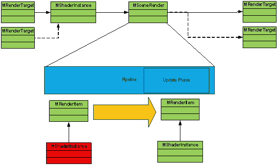
A shader override (MShaderInstance). For all surface shaded objects, the override can be set. MShaderInstances also allow connections to be formed between operations by allowing for MRenderTargets to be passed in as input. In this case, the target is being used for surface shading. An example of this could be for dynamic shadow or environment map rendering.
Figure 46: The scene render’s rendering pipeline has been expanded to show how a render item sent down the pipeline can have its shader instance replaced with an external override. Also shown is the “flow” of render targets as either inputs or specified as the output target.
-
Filtering by “shaded” vs. “non-shaded” (MSceneFilterOption). Shaded is anything that requires shading or lighting. This includes filled drawing for all surface and volumetric shape types (polygonal surfaces, NURBS surfaces, subdivision surfaces, and fluids). Non-shaded includes non-filled/component drawing for all DAG objects, any 3d UI which are part of the Maya scene and any 3d UI which is temporary drawn. Items in this category include wireframe draw, locators, and manipulators respectively.
Note that drawing for MPxDrawOverride is considered to be shaded, whereas for custom render items returned from MPxGeometryOverride, this depends on the associated shader instance and geometry type.
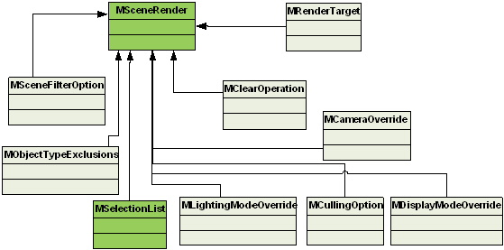
Figure 47: MSceneRender operation and the possible overrides in addition to the base set of overrides on an MRenderOperation (clear, targets, camera override) which are shown without coloring. Light green boxes are constructs which are not classes.
For per scene render preparation, pre and/or post render callbacks can also be specified.
There is no limit on the number of scene operations that can be specified, though there is the inherent cost of rendering multiple types. Each invocation runs the rendering pipeline and thus it is possible to have multiple update and draw phases invoked. The main difference between the new and the old systems is that multiple scene traversals are not invoked, as this is no longer an inherent part of the pipeline logic.
An example of a shaded versus non-shaded pipeline split is show in the following diagram. Each variation in an override can be used to create a different pipeline per scene operation.
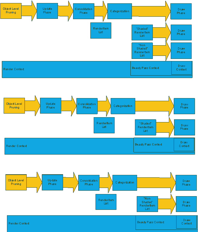
Figure 48: The top-most pipeline is an example of what roughly occurs when there is no separation of “shaded” from “non-shaded”. The split into two pipeline configurations is shown below: a “shaded” only pipeline (middle) and a “non-shaded” pipeline (bottom).
Quad Render
This is a pre-packaged render of a 2D screen aligned geometric quadrilateral. The construct to represent a quad render is MQuadRender.
Depending on the shader and the viewport region specified, the operation can render to fill the entire render target or just part of it. A clear operation (MClearOperation) can be returned from this operation for cases where sub-region rendering is required.
MQuadRender allows for the specification of state setters. By default, when rendering the geometry for a quad render operation, blending is disabled, depth write is disabled, and culling is disabled. Any of the following methods can be implemented by classes derived from MQuadRender to replace the default behavior for a given state:
- virtual const MDepthStencilState* depthStencilStateOverride(); // Override depth-stencil state
- virtual const MRasterizerState* rastersizerStateOverride(); // Override rasterizer state
- virtual const MBlendState* blendStateOverride(); // Override blend state
This operation can be used to render into any of the render targets (MRenderTarget) specified as output by writing the appropriate shader logic for the shader instance (MShaderInstance) associated with the quad operation. As the shader instance can also take, as input, a set of MRenderTargets, a quad operation can form connections between operations via the use of shared targets.
The following is the possible flow of render targets as source data and output data.

Figure 49: The shader instance can take 0 or more targets as input. The shader can write out into 1 or more output targets.
It is possible to render using a render target as both an input and as an output. Depending on device resource management a temporary target may be required. The inherent cost of this functionality should be weighed against any simplification or clarity gained by describing the render loop logic in this way.
“Ping-ponging” of render targets (alternating targets) in general does not create temporary targets. This is due to the fact that the plug-in can explicitly specify different input and output targets to avoid conflicts. For example, a series of quad operations can alternate between using target T1 as a source and target T2 as a destination by writing T1 to T2, T2 to T1, T1 to T2, and so forth. See Post scene render color operations.
For quad rendering, a few basic semantics are provided to allow for automatic binding of parameters which can be used for quad rendering. This includes:
- Viewport pixel size: ViewportPixelSize. The pixel size is sometimes required.
- World view Projection matrix: WorldViewProjection. The matrix required in order for the quad to draw properly in screen space.
- Position and texture coordinates for the geometry of the quad which is automatically drawn by the framework.
In general, as parameter binding is the responsibility of the operation, it can query the available parameters on the shader instance and bind as appropriate. For example render target binding is performed manually.
Example of an invert operation (CgFx)
// World-view-projection transformation.
float4x4 gWVPXf : WorldViewProjection < string UIWidget = "None"; >;

// The single filter input, i.e. the image to be manipulated.
texture gInputTex : InputTexture
<
    string UIName = "Input Texture";
>;

// Filter input sampler.
sampler2D gInputSampler = sampler_state
{
    Texture = <gInputTex>;
    MinFilter = Point;
    MagFilter = Point;
    MipFilter = Point;
};

// Vertex shader input structure.
struct VS_INPUT
{
    float4 Pos : POSITION;
    float3 UV : TEXCOORD0;
};

// Vertex shader output structure.
struct VS_TO_PS
{
    float4 HPos : POSITION;
    float3 UV : TEXCOORD0;
};

// Vertex shader.
VS_TO_PS VS_Invert(VS_INPUT In)
{
    VS_TO_PS Out;

    // Transform the position from object space to clip space for output.
    Out.HPos = mul(gWVPXf, In.Pos);

    // Pass the texture coordinates unchanged.
    Out.UV = In.UV;

    return Out;
}

// Pixel shader.
float4 PS_Invert (VS_TO_PS In) : COLOR0
{
    float4 output = tex2D(gInputSampler, In.UV);
    return 1.0f - output;
}

// The main technique.
technique Main
{
    pass p0
    {
        VertexProgram = compile glslv VS_Invert();
        FragmentProgram  = compile glslf PS_Invert();
    }
}
User Operation
Instead of having a fixed structure for pre and post pass callbacks, a user operation is exposed in the API. The API construct for this is MUserRenderOperation.
The operation is most similar to MViewportRenderer in the old system. The main difference is the level of integration. An MViewportRenderer is an unstructured render override while a MUserRenderOperation is an action which is integrated into the render loop support structure.
A MUserRenderOperation allows for a camera override to be specified, in addition to the viewport and render target overrides inherited from the parent MRenderOperation class.
When querying pass context information if a user operation is active then it's name will be the current pass identifier and the pass will be marked with a "user pass" semantic.
There is one entry point which is exposed to "execute" the operation. In order to have some frame of reference a draw context (MDrawContext) is provided.
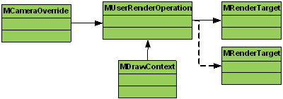
Figure 50: The camera can be overridden for a user operation. At execution time, an MDrawContext is provided. The output can be directed to one or more render targets.
As with all plug-ins which affect draw state via direct API calls, the operation should always restore to the entry state. This is especially important in relation to the current output target(s). State such as the active OpenGL context, FBO, PBO should not be set within the operation, and if they ever are, then the previous values must be restored on exit from the operation.
For example, calls such as M3dView::beginGL()/endGL() should never be called since they set active OpenGL context. Also, they never run under DirectX or in batch mode.
Present Operation
To present a render target for interactive viewing a present operation is provided. In the API this is represented by MPresentTarget.
This is roughly equivalent to a swap buffers call in OpenGL or a present of a SwapChain in DirectX.
When batch rendering, this operation has no meaning and is automatically ignored.
The operation can specify a color render target to be displayed. If none is specified, the active internally set color target is used. It is possible to optionally specify depth to be presented. If a depth target override is specified then the depth values from that target are copied to an onscreen depth target.
When dealing with active stereo rendering the output can be directed to the left or right eye. The way to achieve this in the render loop is to present the contents of a render target to the left buffer", and the contents of a render target to the right buffer. Mono viewing, which is the default, is achieved by specifying rendering to the center buffer.
If active stereo rendering is supported by the video card, and the driver has been appropriately set up, then the MTargetBackBuffer input can be set to route targets for display as appropriate.

Figure 51: The back-buffer option can be set to override the output buffer. The “present” operation routes the appropriate render target to the correct buffer on the “on screen target”.
HUD Render
This operation allows for the display of the 2D HUD for a 3D viewport. In the API, this is represented by MHUDRender.
Structure Summary
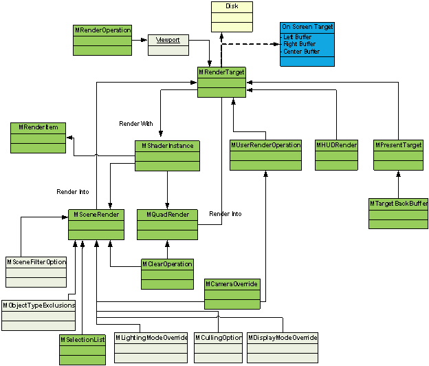
The above diagram shows the overall structure of all of the various operations and how various overrides and resources (shader instances, render targets) can be shared and reused.
The connection from the MShaderInstance to an MRenderItem, though not explicitly part of the render loop structures, shows the possible flow of data (render targets or textures) from the output of a render loop (pipeline) to the input for a render item flowing down another pipeline. An example of this is to provide shadow maps as an input to shaders which render an item with shadowing.
Override Setup And execution
With a basic understanding of the available operations, this section shows how a plug-in should set up the override to ensure proper configuration and execution of these operations.
The term phase introduced when discussing the rendering pipeline is reused here to describe the key functionalities of a plug-in. The basic phases are: setup, execution and cleanup.
- MRenderOverride::setup() is called.
- Regardless of the render loop, the logic needs to be translated into a list of operations. This is not defining the logic but rather preparing the appropriate operations. Generally all operations can be statically allocated once and reused across frames, though it is possible to allocate and return operations dynamically during the execution phase.
- Any data which should be persistent across the frame render (global to all operations) should be evaluated at this time.
- All texture and target allocation needs to be done at this phase. This includes handling any resize of custom render targets. Generally, all textures and targets can be statically pre-allocated once and updated as required.
- Shader instance allocation needs to be done at this phase. Parameter updates can be done at this phase or when the shader instance is updated for an operation. Generally, all shaders can be statically pre-allocated once and reused as required.
- In general, any DG or DAG updates should only be performed in this phase. This includes determining selection lists for scene filtering, determining which camera(s) to use and so forth. As the override is being performed within a frame render, actions like DG time change should not be performed, but instead should be triggered at a higher level.
- For interactive 3d viewport rendering, any access to classes such as M3dView should all be done at this phase. The required information should be extracted and passed to operations a necessary.
- A set of methods are called on the override to iterate and return the operations which should be called in sequence. (startOperationIterator(), renderOperation(), nextRenderOperation()). This provides the framework with knowledge to set up the appropriate pipelines to be executed. There are an unlimited number of possible configurations with various levels of complexity. It is up to the plug-in code to determine which operations should be returned here. As an example, stereo rendering is supported as a plug-in, and the logic is setup to allow for different configurations to be performed based on stereo display mode.
- Once this operations list is specified, operations cannot be created nor deleted until they have finished executing.
- Each operation is called independently and in the sequence specified by the plug-in. If a custom derivation has been created, then virtual overrides are called to query for data required at the time the operation executes.
- Some operations require shader instances to be returned. If the parameters on the shader instance need to setup per operation invocation, the update should be done here.
- As operations are independent, co-dependent data should be avoided if possible. In addition, one operation should avoid modifying another operation while it is being executed.
- Any temporary per-frame references should be released or reset here. For example, any selection list, DAG paths or node references should be reset.
- A good practice is to reset operations to their default state which also clears out any external references.
Instances of render overrides and operations have no implicit resources themselves, but instead only keep references to external resources. It is the responsibility of the plug-in to determine the life-time for these resources. It is best to use the available resource managers if possible. As long as the plug-in holds on to a reference to a resource, it remains allocated. Resources which are passed back to an operation (for example through an MDrawContext) should never be held on to as it could be a resource which only exists during the lifetime that the operation is being executed.
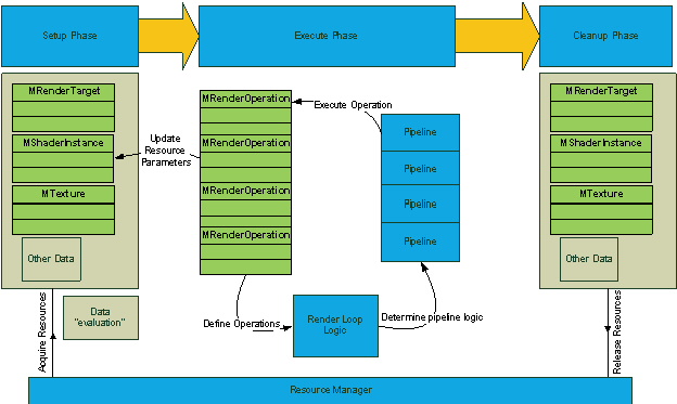
Figure 53: A high level breakdown of the override “phases”: up-front data evaluation and update, execution time logic definition and operation invocation, and the final cleanup. One or more pipelines may be setup and updates to operations can represent changes to operation data dependencies. For example, the render target used by a shader instance parameter can change during execution time.
Render Override Examples
In this section, a few example operation configurations are described.
Post scene render color effect
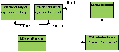
This example shows a basic scene render into depth and color output targets. The second operation applies a color effect (for example, “posterize”) to the color target from the first operation and writes back into the same target. This is similar to allowing reading and writing to the same color target. The implementation can follow the example above; or, a second color target can be acquired and used as the destination for the color effect, or a color target can be not specified at all. In the latter case, the active internal color target is used.
Glow example
A more complex configuration which is used to support a “glow” post effect is part of the viewRenderOverride SDK sample.
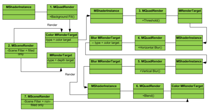
Figure 55: In this example, the threshold of the original scene render is based on an intensity value. The result is blurred using a 2-pass filter and then combined with the original image to provide a very rudimentary “glow” effect. The user interface elements are drawn last. The original depth buffer is used to provide proper UI and non-UI element compositing.
Stereo rendering
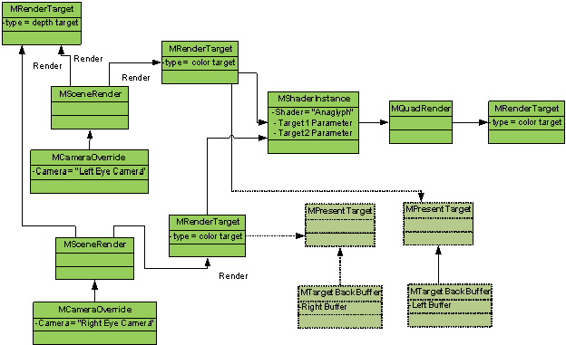
This is an example from the plug-in which is used to support stereo display. On the left are two scene renders which are the first two operations. Each scene render uses different camera overrides to render from the left and right eye (camera). The output is passed to two color targets in order to perform a final composite based on two color inputs. The depth target is reused as the final contents are not required. At the top right a quad render operation is specified as the next operation in order to support Anaglyph passive stereo display. Different shaders can be returned dynamically for the quad operation, depending on the required final passive stereo display mode. Active stereo is shown at the bottom right. It would be an alternative operation configuration that passes the left and right color targets to the left and right onscreen buffers respectively.
Beauty pass color composite
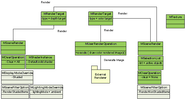
This example shows how an external renderer, which only generates color images as output, can be composited with the rest of the scene rendered using the internal framework.
There are three basic operations performed:
- The first (left) MSceneRender prepares the depth buffer with depth values based on shaded objects in the scene. The display mode is set to be shaded and the scene filter is set to only draw shaded items. There are a few choices for the shader used. Either a custom depth shader can be applied; or, as shown in this case, a solid color shader using an ambient light can be used. The color mask is set to only write to a depth target.
- The next operation (MUserRenderOperation) is used to blit the external renderers color image only to the color target.
- The last operation (right) MSceneRender is responsible for overlaying the non-shaded scene elements. Here, only the active Maya objects are rendered. No targets are cleared but depth testing is still enabled to support proper shaded versus non-shaded scene compositing (for example, “wireframe-on-shaded”).
Multiple render targets
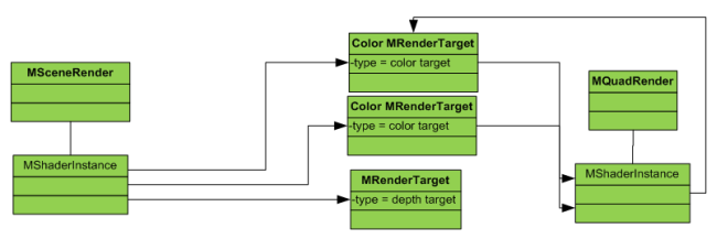
A simple example of multiple color target usage is found in the viewRenderOverrideMRT sample plug-in. Here, a single scene render uses a shader override to output position and normal values to two different color targets at the same time. To visualize the results, an additional quad render option takes the two targets as input into a shader which blits the two target contents side-by-side. The result of the quad render operation is written to one of the two existing color targets. A “present” operation is then used for displaying to the viewport (not shown above).
Depth and color render compositing
In the case where an external renderer is used, and directly rendering into existing targets is not desired (or not possible), the recommended approach is to render to an intermediate target or texture.
These intermediaries can be then blit to the final targets used for display. Once this is done, as long as depth has been properly prepared, any additional UI elements that the external renderer does not handle can be composited.
The following are sample images for a Maya scene, rendered with the mental ray renderer. Shown is the final color (beauty) image as well as the corresponding depth image (remapped to 0..1 grey scale from the original values).

The simple pipeline found in the sample viewImageBlitOverride plug-in is shown in the diagram below:
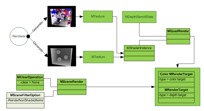
The rendered images are taken and read as color and depth textures accordingly. A single quad render uses a shader to blit the textures to the color and depth targets. After this is done, a scene render is used to optionally depth composite the “UI” elements. Here, the clear is disabled, and a filter applied to ignore shaded render items.
Assuming that the original scene used to create the render is loaded into Maya, the result could look as follows. The wireframe and IK rendering are all done by the scene render pass.
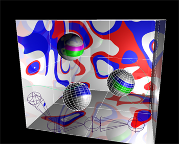
The MQuadRender operation uses a state setter override. By default, when rendering the geometry for a quad render, alpha blending, depth-write, and back-face culling are all disabled. Any of the following methods can be implemented by classes derived from MQuadRender to replace the default behavior for a given state:
- virtual const MDepthStencilState* depthStencilStateOverride(); // Override depth-stencil state
- virtual const MRasterizerState* rastersizerStateOverride(); // Override rasterizer state
- virtual const MBlendState* blendStateOverride(); // Override blend state
In this example, a depth stencil state instance was created which enables depth-write, and sets the depth compare to be “Always”. The instance is then returned by overriding the depthStencilStateOverride() method.
Another possibility (not show in the plug-in example) is to add an additional scene render for non-UI objects that the renderer does not render. Basic filtering by object type can be used. For example, plug-in objects may not be handled by the renderer, in which case they can be composited in another pass. The level of integration of compositing may vary.
In general, an integration that renders both color and depth does not integrate with internal hardware post-effects such as screen-space ambient occlusion. Any operation that only draws UI does not have post-effects enabled. Additional non-UI scene renders can disable post-effects as part of the operation.
User operation with device access
This is a simple configuration from a render loop logic perspective. Its logic is closest to the free-form MViewportRenderer implementation from the old system. There is only one MUserRenderOperation. The SDK example viewDX11DeviceAccess shows how various resources can be allocated from the framework and how GPU handles to the render targets and texture (shader resource views), state blocks, sampler states can be extracted. The older MDrawTraversal interface is used to scan the entire scene to draw some bounding boxes.
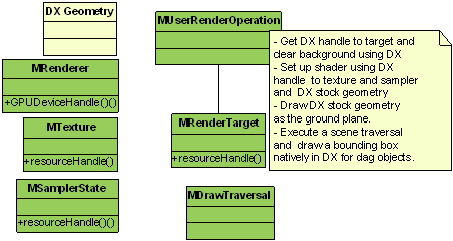
Figure 62: In the setup phase the GPU device handle is extracted to create some stock DX geometry. A texture and a sampler state are allocated via the appropriate manager in the framework. An output target is also allocated. During the execution phase, a series of steps is performed to get the GPU handles of resources and rendering is all done using native DX calls.
Render target / frame caching
It is sometimes desirable to cache or save rendered frames. For example, you can store frames on disk for the playback of an animation or for manipulation in another application. The example in this section shows how a render override can be used to cache viewport frames in memory for faster playback.
The following figure shows the complete set of actions in a system which can either cache frames or playback cached frames. Each color coded area represents a logical sub-set of available actions. Resources are colored in green.
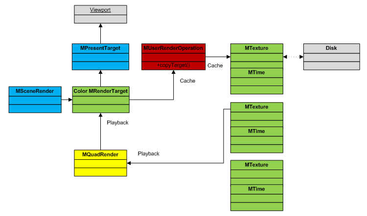
Figure 63: Diagram illustrating the following: regular refresh (blue boxes), a frame cache (green boxes), and render pipeline operations that perform either caching (red boxes), or scene render replacement in playback (yellow boxes). The present operation is shown as a possible final viewing output. Output could also be serialized to disk. Outputs are represented in grey boxes.
During an animation playback, the scene is rendered to the viewport for each time step. The two operations are represented by blue boxes: an MSceneRender to render the scene into a color render target and a MPresentTarget to display the color target in the viewport. The render target contents are only valid at the current time. Whenever the current time changes, new content must be drawn to the target.
To avoid this redraw, the contents can be cached. In the diagram, we show a simple cache where each cache element references a hardware texture (MTexture) and a frame time (MTime). Each of these elements could be serialized to disk.
With this structure, a snapshot (or copy) of the render target can be taken at the desired time frames. In this implementation, a user operation (MUserRenderOperation, shown in red) executes after the scene render. The operation makes a hardware copy of the render target to a texture (MTexture). The convenience method MDrawContext::copyCurrentColorRenderTargetToTexture() is used in the implementation to produce this cached texture. You can also perform this copy within the post render (postRender()) method on the MSceneRender.
The caching operation flow of data is shown via the links labelled Cache.
To stop re-rendering the scene during playback, the scene render operation is replaced by a quad render operation (MQuadRender, shown in yellow). This operation determines if a frame (texture) has been cached for a given time frame. If one is found, then it draws that texture back to the color render target. The present operation can still be executed as before. The playback flow of data is shown via the links labelled Playback.
The code for this example can be found in the viewRenderOverrideFrameCache SDK example in the Developer Kit.
Multiple Pass Scene Rendering
The following example demonstrates how the multiple draw interface (found in the MPx3dModelView class in the Legacy Default Viewport only) can be performed in Viewport 2.0 using a render override.
In this example, instead of a draw, a scene operation can be executed. In this case two scene operations are shown.
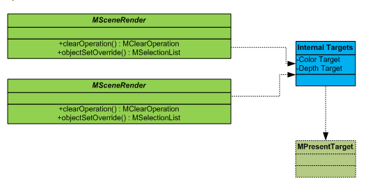
Figure 64: Operations that are implemented in the plug-in are shown in green. The present operation (in lighter green) is optional. To override the clear and object set methods, a new class is derived with different return parameters for each method depending on the desired execution sequence and filter options.
The first scene operation clears the background via the clearOperation() method’s return value. If a subset of objects is to be drawn, then the objectSetOverride() method returns an appropriate value.
The second scene operation (shown below the first in the diagram) indicates not to clear the background. This allows for drawing to be cumulative.
The final operation that can optionally be executed is a present operation. This step is needed if presenting the results to the active interactive viewport.
Internal Targets indicates that rendering is drawn to the current internal color and depth targets, and is the source target for presentation.
The Developer Kit example viewObjectSetOverride provides the source code that implements this scenario. The example queries the contents of two Maya sets. The first scene operation renders a first set, and the second scene operation a second set.
Post scene render color operations

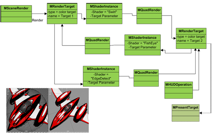
This example shows how a series of 2D color operations can be performed after a scene render. Refer to the viewRenderOverridePostColor developer kit example for more details.
In this plug-in example, there are three 2D quad operations (MQuadRender), each using a different shader (MShaderInstance). The scene render is stored in a custom target (labeled Target 1 in this figure). This target is used as input to a second target (labeled Target 2). The next color operation takes Target 2 as input and route it to Target 1. Subsequent color operations will alternate between using Target 1 as the source and Target 2 as the destination targets by writing Target 1 to Target 2, then Target 2 to Target 1 and so forth.
After the color operations are performed, the HUD is drawn using a HUD operation, and a present operation presents the output target used by the last color operation.
The associated image shows only the quad operations with the shaders Fish-Eye and Edge-detect enabled.
