These are the attributes in the strokeShape node you set when working with Paint Effects.
Related topics
-
Paint different ways in 3D
- stroke
-
Contains the default name of the strokeShape node.
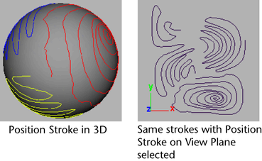
Position Stroke
This option is only useful on strokes painted on objects. It has no effect on strokes painted on the view plane or grid plane of the perspective view. You can use it to create textures from strokes painted on 3D objects (for details, see Create textures from painted 3D objects). Select one of the following:
- in 3D
-
Displays the stroke on the surface, as painted.
- on View Plane
-
Displays the stroke between 0 and 1 in world space on the XY plane (near the origin). Think of this space as a texture map—each point on the texture corresponds, or maps, to a point on the paintable surface. Any strokes on the surface are drawn in this area. However, when you do a post-process render, the strokes render on the view plane.

- Display Quality
-
Use this to set the display quality of the wireframe for the selected strokes. The higher the percentage, the more closely the stroke wireframe represents the rendered stroke. For more information, see Modify stroke display quality.
- Draw As Mesh
-
With the Draw As Mesh option, you can preview the rendered look of your strokes interactively in the scene view; you don't have to view them in the Paint Effects panel. With Draw As Mesh turned on, you can see the Paint Effects strokes in the scene very close to what they will be when rendered. You can tumble around and see what they look like from any camera view, and you can model on other objects in the context of the Paint Effects in the scene. If you want to do any modeling on the stroke objects, you need to convert them from Paint Effects to polygons. One of the biggest benefits of working with Draw As Mesh turned on is that you can edit brush attributes and see the changes happening to the stroke (Paint Effects shape) in the scene view.
The drawing of Paint Effects strokes in the scene view is much faster than the stamp draw in the Paint Effects panel. You can draw all Paint Effects as polygons in three ways:
- Select Display > Rendering > Paint Effects Mesh Display (see Rendering Options).
- Select strokes and turn on Draw As Mesh in the strokeShape Attribute Editor.
- Select Draw As Mesh in the Paint Effects Tool Options ().
Notes:
- When Draw As Mesh is turned on, it may be somewhat slower than line draw, particularly during playback when the brush or painted object has animation.To speed up playback, either turn off Draw As Mesh or decrease the Display Quality, which has no effect on the rendered output.
- Using Draw As Mesh with Paint Effects Hair does not provide more useful information and may in fact be slower. The line draw is as good or better for Hair.

- Sample Density
-
As you paint, Paint Effects samples points on the stroke. At each sample point, Paint Effects “plants” tubes, grows previously planted tubes by a segment, and applies paint stamps to the stroke. You can adjust the number of sample points after painting the stroke by changing the Sample Density. The default density is 1. Increasing the density increases the number of samples.
For example, suppose you have two strokes painted with the same template brush settings, the first which was painted very quickly, and therefore has few sample points, and the second which was painted very slowly, and therefore has many sample points. The strokes will look quite different. You could make the first stroke more similar to the second by increasing its sample density.
- Seed
-
This option sets the sequence of random numbers used for brush attributes that are randomized (for example, tube length and width, and HSV values). By default, each stroke you paint has a different seed number to ensure that strokes with identical attributes and randomization values look different. Setting a different seed number for a stroke will apply a different set of random numbers to the randomized attributes, making the stroke look different. To make otherwise identical strokes look the same, use the same seed number.
- Draw Order
-
Set the order that strokes paint in the scene. You may want to change the draw order to layer different types of strokes (for example, you could paint opaque strokes first, then transparent strokes). Strokes with lower numbers draw first, followed by strokes with larger numbers. By default, all strokes have a draw order of 0.
- Surface Offset
-
Set the distance (in world units) you want to offset the stroke from the object or plane it’s painted on. For more information, see Surface Offset in the Paint Effects Tool Options.
- Smoothing
-
The path of a stroke is defined by an underlying stroke path curve which is comprised of CVs. Just like using the Pencil Curve Tool, painting a stroke can create irrelevant CVs. Use this option to dampen the effects on the stroke path curve of spurious or misplaced CVs by recalculating the smoothest path through the CVs.
Specify the amount of smoothing to be calculated. A Smoothness setting of 0 causes no smoothing.

You can also use smoothing to soften the transition between multiple surfaces.
 Note: Although smoothing does not alter the number of CVs, you can also smooth strokes by removing CVs. For information, see Simplify stroke path curves.
 - Motion Blurred
-
When you render an animation, motion blur gives the effect of speed and movement by blurring objects in the scene. When Motion Blurred is turned on, the stroke will appear blurred. If Motion Blurred is turned off, it will appear sharp. You must also turn on Motion Blur in the Motion Blur section of the Render Settings window. For details, see the Motion Blur section of Render Settings: Maya Software tab.
- Primary Visibility
-
When Primary Visibility is turned on, the stroke is visible in the view and renders. When its turned off, the stroke is visible in the view but it does not render. If Primary Visibility is turned off and Cast Shadows is turned on (see Cast Shadows in Shadow Effects brush settings), the stroke’s shadow renders.
End Bounds
These are the stroke Shape attributes in the End Bounds section.
- Min Clip
-
Specify the point along the stroke that defines the beginning of the stroke segment. When the Min Clip value is 0, the beginning of the stroke is not clipped.
- Max Clip
-
Specify the point along the stroke that defines the end of the stroke segment. When the Max Clip value is 1, the end of the stroke is not clipped.
Normal Direction
These are the stroke Shape attributes in the Normal Direction section.
- Use Normal
-
Turn on Use Normal to use the normal defined by the coordinates set below the option. If Use Normal is off, strokes painted on objects use the surface normals, strokes not painted on objects use stroke path curve normals.
- Normal
-
Specify the direction of the normal. This normal is used only when Use Normal is turned on.
Pressure Mappings
These are the stroke Shape attributes in the Pressure Mappings section.
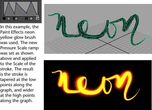
- Pressure Scale
-
Use this graph to edit the line width along a stroke (as well as other pressure controlled attributes). This is great for tapering strokes and getting a “sketching” look.

- Pressure Map 1, 2, and 3
-
Select which value you want to map to pressure. You do not need to map all three brush attributes to stylus pressure. Select Off for no pressure sensitivity.
- Pressure Min 1, 2, and 3
-
Set the minimum pressure at which the pressure mapping will start to take effect. The minimum attribute value that you can paint is determined by multiplying the Pressure Min by the value set for the mapped attribute. For example, if you map Tube Length to pressure, and the tube length for the stroke is 3, and the Pressure Min is 0.5, no matter how lightly you press on the stylus, the tube length will never be less than 3 x 0.5, or 1.5. Use the lowest minimum pressure possible to increase the range of the mapping.
- Pressure Max 1, 2, and 3
-
Set the maximum pressure at which the pressure mapping will take effect. The maximum attribute value that you can paint is determined by multiplying the Pressure Max by the value set for the mapped attribute. For example, if you map Tube Length to pressure, and the tube length for the stroke is 3, and the Pressure Max is 2, when you press as hard as possible, the tube length will be 3 x 2, or 6.
Input Curves
These are the stroke Shape attributes in the Input Curves section.
- Path Curve
-
This contains an array of curves to use as the stroke path, along with a number of points to sample along each curve. The curves are sampled in the order they appear in this list to produce a single set of output points and normals which define a poly line path for the Paint Effects stroke. By default the resulting points will correspond to the list of points sampled while you painted the stroke. If the stroke crossed multiple surfaces there will be a separate curve created each time you paint across a surface boundary.
Mesh Output
These are the stroke Shape attributes in the Mesh Output section.
- Color Per Vertex
-
Use this to control the color per vertex. The default is None. Other options in the drop-down list include Color and Illuminated.
- Hard Edges
-
When turned on, this affects the lighting of the object and makes the edges around tubes hard when using the Brush Type.
- Output Quads
-
Output to quads or triangles. The default is off, defaulting output to triangles.
- Poly Limit
-
This value indicates that when converting the Paint Effects stroke to polygons, it should stop after it has reached approximately this number of faces. This can be used to avoid creating excessively large meshes that could cause you to run out of memory. The default is 100 000. A value of 0 indicates no limit.
- Camera Point
-
If Forward Twist is turned on, then when you convert Paint Effects to polygons the perspective camera is connected to this attribute so you can maintain the twist on the polygons when the view changes.
Mesh Vertex Details
These are the stroke Shape attributes in the Mesh Vertex Details subsection of the Mesh Output section.
- Main Vertex Buffer, Leaf Vertex Buffer, Flower Vertex Buffer
-
These attributes keep track of how many vertices were created the last time the polygon mesh was evaluated. They are used to preallocate the right amount of memory.
NURBS Output
These are the attributes in the NURBS Output section.
- Degree
-
The degree of the final generated output curve.
- Curve Align
-
This enables tangent continuity across output curves where branches meet.