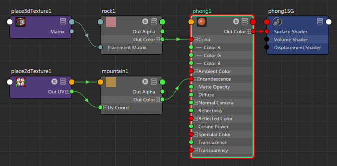
Connections between node attributes are shown by colored connection lines in the Hypershade. The connection lines between nodes indicate what type of data flows through the connection. Depending on the types of nodes and connections used, different information is passed. That is, values may be of color, distance, position, angle or object ID.

Some information can come as a single value (for example, OutAlpha is a single value) or as triple (for example, an Out Color RGB value or an XYZ value). Triple connections are represented by green connection lines. Single, double, triple, data, and array data each have an assigned default color.
The Hypershade and the Node Editor share the same connection line colors. To change the default colors, select Windows > Settings/Preferences > Color Settings and adjust the colors in the Node Editor section.
Each node has a default attribute and a list of commonly connected attributes that lets you make node connections interactively. To allow for an efficient workflow, when you first create a node in the Hypershade, its most commonly used attributes are displayed . To connect render nodes, middle-mouse or left-mouse drag to create connection lines between your output and input attributes. You can also Ctrl+middle-drag a node onto another to connect nodes using their default connections. See Connect nodes by dragging connection lines.