When setting up for velocity controlled valve gate simulations, there are some modeling guidelines to consider.
Velocity controlled valve pins are supported for the following mesh types:
 Midplane
  Dual Domain
- The valve pin tip, that is, the section that comes into contact with the gate channel when fully closed, is assumed to follow the gate channel geometry for velocity controlled pin movement.
Valve pin tip
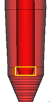
- The small end of the valve pin is assumed to be flush with the end of the gate.
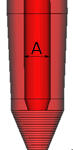
- The nominal pin diameter must be specified and refers to the diameter of the cylindrical pin, before it tapers to fit the gate opening.
Nominal pin diameter (A)
- Any pin tip geometry, that cannot be accounted for by the nominal pin diameter and the gate channel geometry, is ignored.