Boundary Conditions are the final settings that define the physical boundaries of the molding setup.
Boundary Conditions range from the injection location on the feed system, to coolant inlets on the cooling channels, to loads or constraints on the part. They are assigned an identification label to enable you distinguish them from each other and from other modeling components.
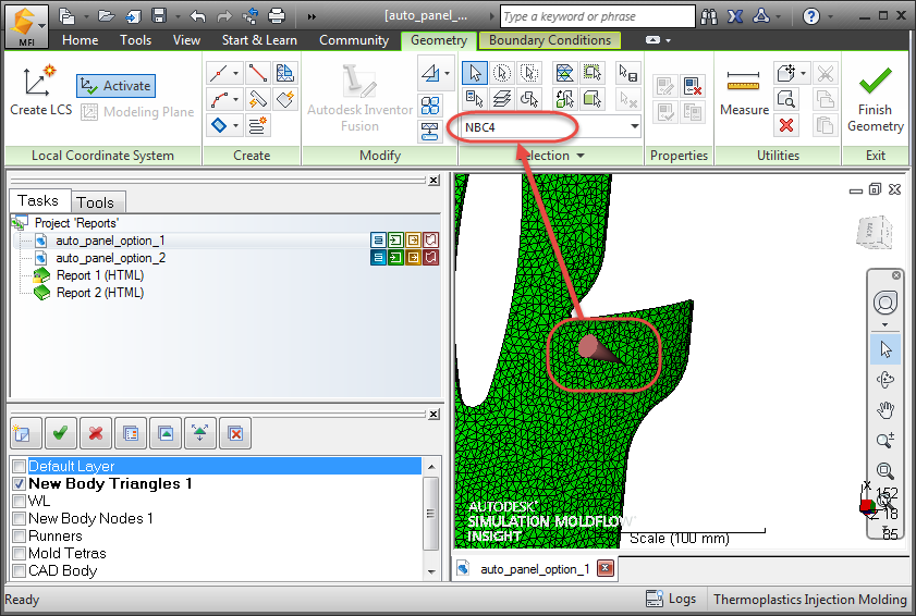
- Nodal boundary conditions
- Nodal boundary conditions include everything except loads. For example, injection locations, valve gates, gas entrances, coolant inlets and coolant outlets are all nodal boundary conditions. On occasion, they are applied to the part geometry; otherwise they are applied to the mesh. Each nodal boundary condition has a unique identification label, comprised of the letters 'NBC' followed by a number. When you select boundary conditions, their identification numbers appear in the selection list.
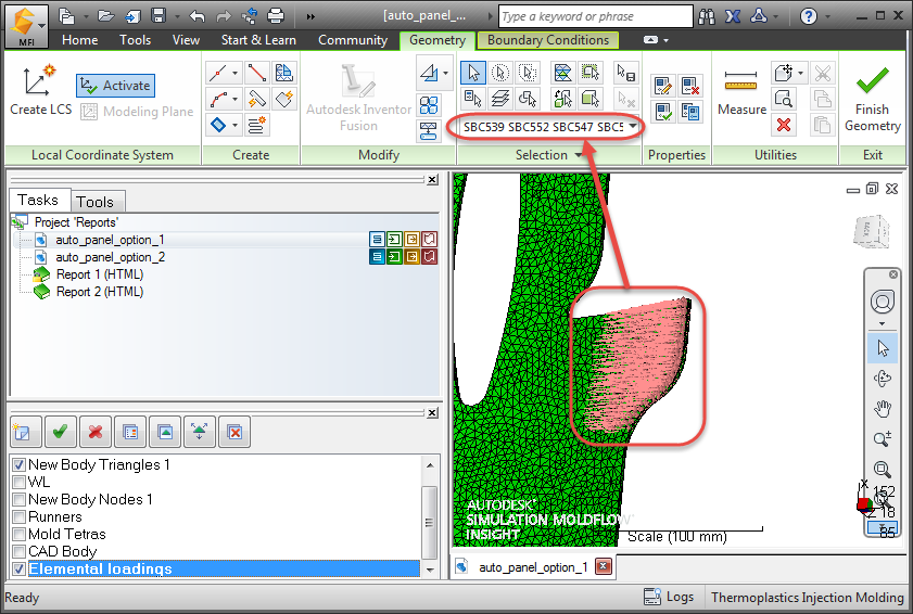
- Surface boundary conditions
- Surface boundary conditions refer to those loads that are applied directly to triangles. Each surface boundary condition has a unique identification label, comprised of the letters 'SBC' followed by a number. When you select boundary conditions, their identification numbers appear in the selection list.