Introduction
In this exercise, we continue our work with the lever arm model. We'll use contacts and symmetry to define a more realistic representation of the physical model.
Using Contacts Instead of Boundary Conditions
It is important to realize that every interaction idealization involves certain "gives" and "takes". Most often the "takes" involve speed and simplicity. The "gives" involve compromises in the response at the interaction.
A "perfect" idealization produces exactly the same response at the interaction as the physical parts. The key is to balance accuracy speed and modeling simplicity with an acceptable amount of variance from the true physical response. You should consider how much variance is acceptable versus how much is unavoidable. It is a good idea to quantify these with bracketing studies.
The "Rule of Differential Stiffness" can be very useful for determining the best way to model certain reactions:
- If the stiffness of the part of interest is MUCH LESS than that of the supporting parts, use Constraints.
- If the stiffness of the part of interest is MUCH MORE than that of the supporting parts, use Loads.
- If the stiffness of the part of interest is SIMILAR to that of the supporting parts, add the supporting parts to the model, and use Contacts.
In this exercise, the lever and the pins have similar stiffness values. Therefore, we are going to use contacts to simulate their interaction!
Symmetry
Symmetry is an important modeling technique that allows you to analyze a fraction of the structure without sacrificing quality. In some instances, as shown in this exercise, it is a better technique for improving solution quality than other methods.
In the previous exercise with the lever arm, the lever can still slide along the length of the pins. In a linear static analysis, however, rigid body motion is not permitted. Here are several options to consider:
- Enable friction with the contact definition to provide resistance to the sliding movement. This method is sensitive to the contact force, and can slow down the analysis.
- Connect the lever to the ground or connect it to a pin using a soft spring (connector). This adds an additional step, but does not affect the solution time.
- Place or create a point on the geometry at the symmetry plane, and constrain this in the direction of free motion.
- Use symmetry in the model to constrain the rigid body motion. This method reduces the model size while naturally adding the needed constraint!
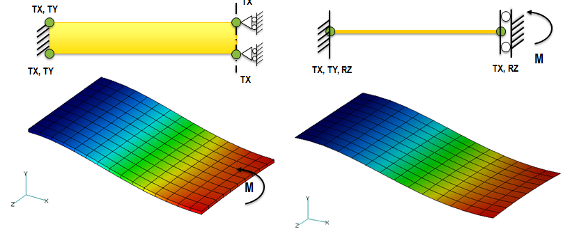
Symmetry constrains the "plane normal" translations and "in-plane" rotations:
1. Open the Model
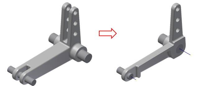
Start Autodesk® Inventor, and open the file Lever-Pins.iam from the Section 10 - Contact & Symmetry sub-folder of your training exercises folder. Note that the model has been cut in half with an extrusion cut. This is valid because the geometry on either side of the plane of symmetry is exactly the same:
From the Environments ribbon tab, click Autodesk Nastran In-CAD.
2. Assign the Physical Property to the Lever Arm
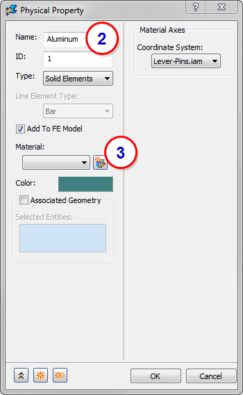
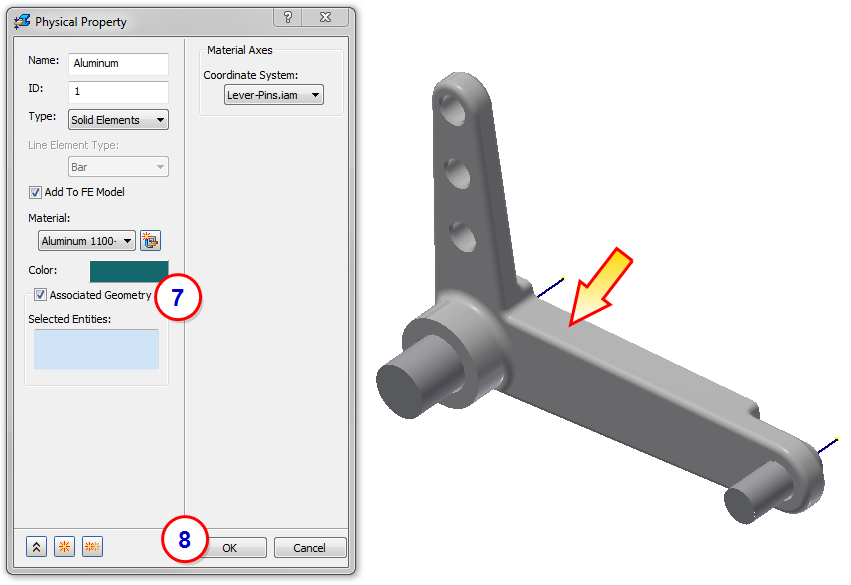
- From the Properties panel of the ribbon, click Physical.
- On the Physical Property dialog, enter the name Aluminum.
- Click the New Material icon.
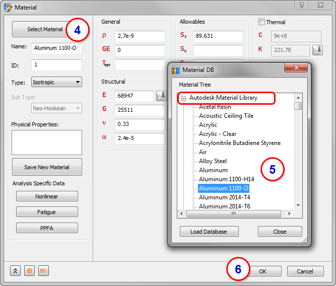
- On the Material dialog, click Select Material.
- On the Material DB dialog, expand the Autodesk Material Library, and select Aluminum 1100-O. Click Close.
- Click OK on the Material dialog.
- On the Physical Property dialog, check Associated Geometry, and select the lever arm part.
- Click OK.

3. Assign the Physical Property to the two Pins
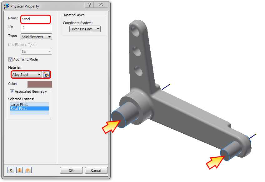
Repeat the procedure in the previous step, with the following changes:
- Name the property Steel.
- Select Alloy Steel from the Material DB list.
- Assign it to the two pin parts:
4. Constrain the Pins
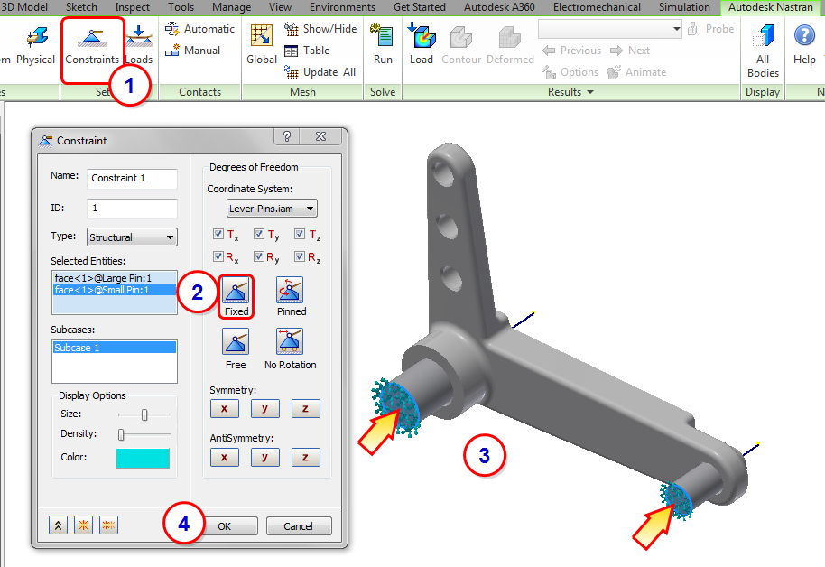
- Click Constraints from the Setup panel of the ribbon.
- Click the Fixed button on the Constraint dialog.
- Select the end surface of the two pins.
- Click OK.
5. Assign the Symmetry Constraint
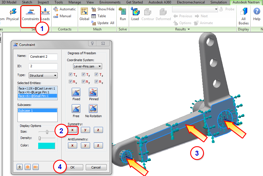
- Click Constraints from the Setup panel of the ribbon.
- Click the X Symmetry button. (Note that the normal to the plane of symmetry is in the x-direction. Choosing X Symmetry constrains TX, RY, and RZ.)
- Select the three faces on the symmetry plane. (Be sure to select the surface on the lever and one on each pin.)
- Click OK.
6. Assign the Load
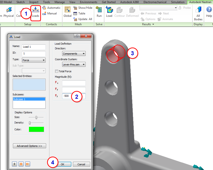
- Click Loads from the Setup panel of the ribbon.
- Enter a load of -500 for Fz. (Because we are using half symmetry, we only need half of the original load.)
- Select the surface of the top-most hole.
- Click OK.
7. Assign Contacts
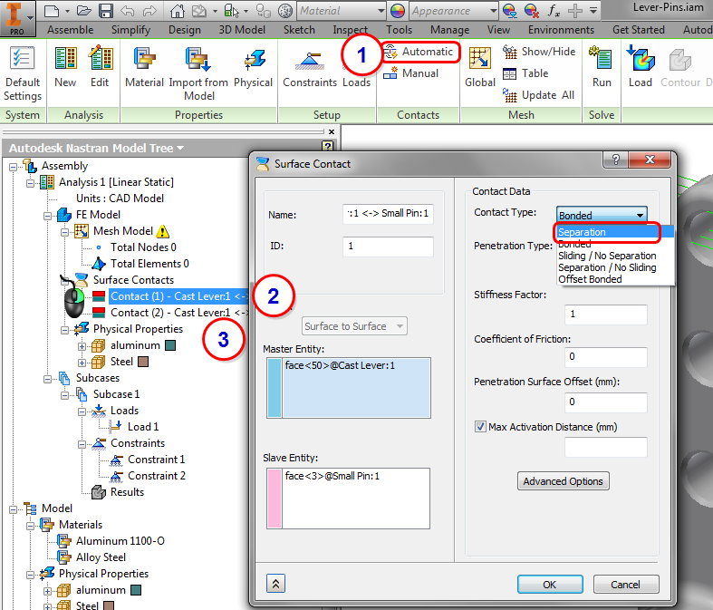
- Click Automatic from the Contacts panel of the ribbon. (This automatically identifies and assigns the surface contact pairs throughout the assembly.)
- The default contact type is Bonded. However, for this assembly, we want to allow for some movement. To change the contact type, right-click on the first contact in the tree, and click Edit. In the Surface Contact dialog, select Separation.
- Repeat with the other contact.
8. Mesh the Model
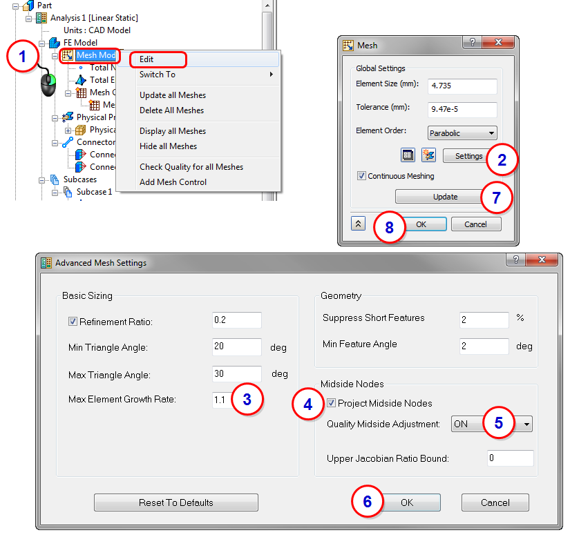
- From the Part tree, right-click on Mesh Model, and click Edit.
- From the Mesh dialog, click Settings.
- On the Advanced Mesh Settings dialog, change the Max Element Growth Rate to 1.1.
- Check the Project Midside Nodes box.
- Set Quality Midside Adjustment to ON.
- Click OK to close the Advanced Mesh Settings dialog.
- Click Update to re-generate the mesh.
- Click OK to close the Mesh dialog.
9. Run the Analysis
Click Run from the ribbon.

10. Review Displacement Results
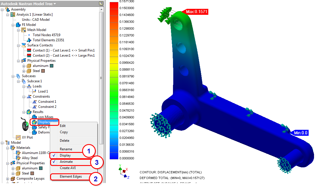
- From the Results branch of the tree, right-click on Displacement, and click Display.
- To hide the element edges, right-click again on Displacement, and uncheck Element Edges.
- To animate the displacement, right-click again on Displacement, and check Animate.
11. Review the Stress Result
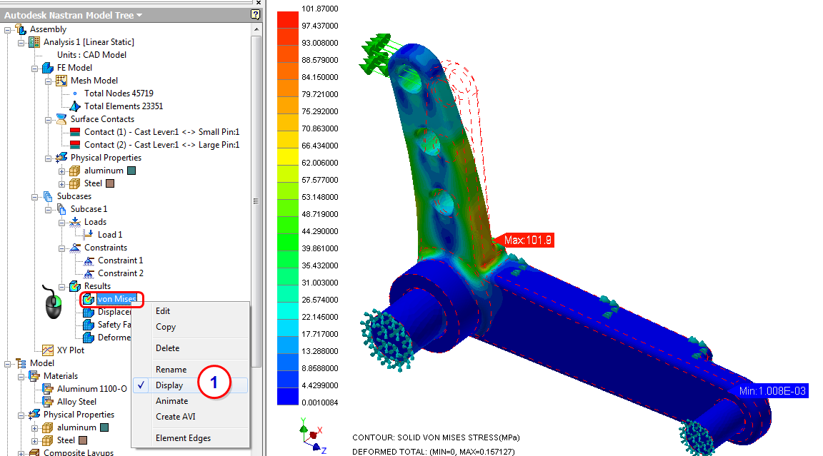
- From the Results branch of the tree, right-click on von Mises, and click Display.
12. Review the Safety Factor Result
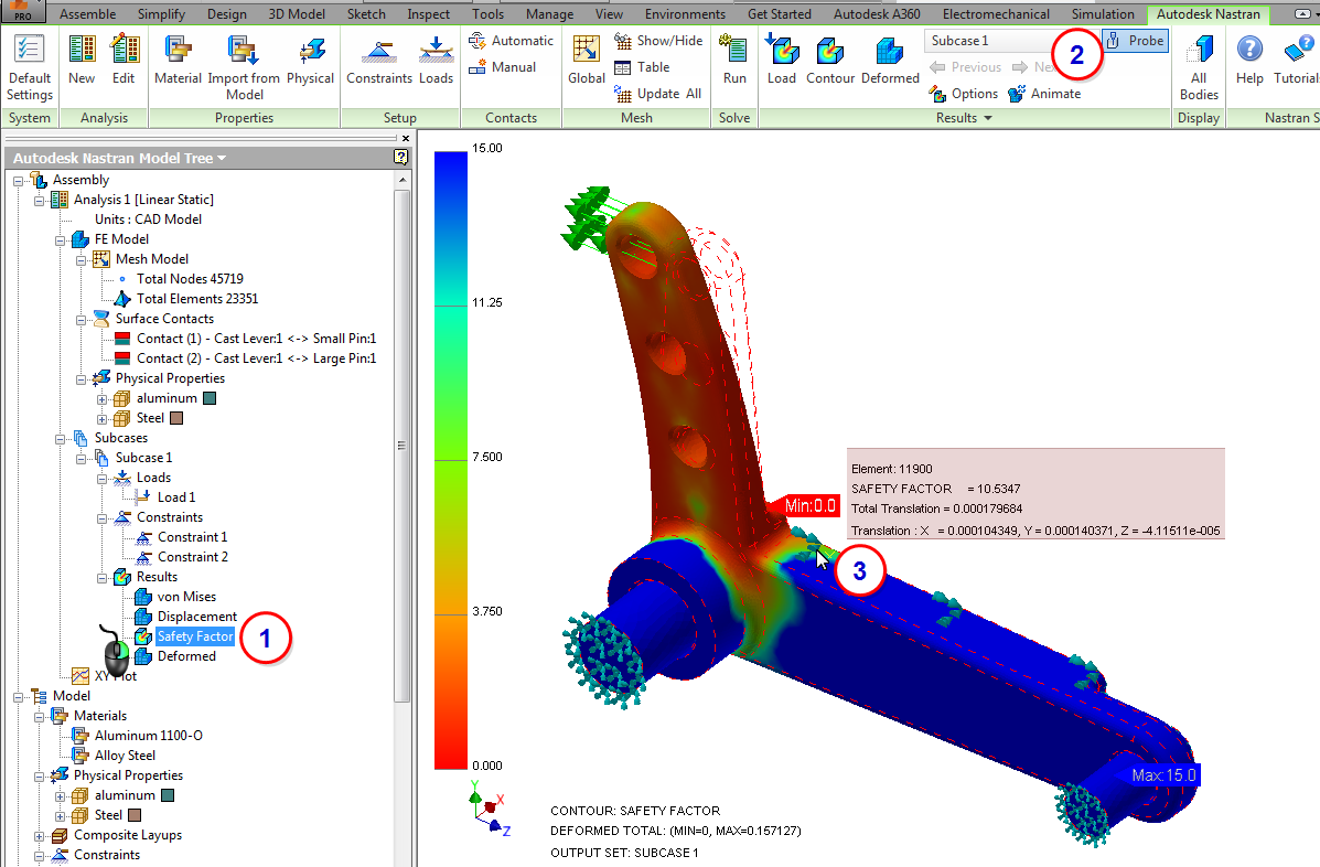
- From the Results branch of the tree, right-click on Safety Factor, and click Display.
- To determine the exact value of safety factor at a specific location, click the Probe command.
- Hover over the model.
Summary
In this exercise, we modeled contact using the Automatic contact assignment. We also applied Symmetry Constraints to the cut face to remove lateral (X) rigid body motion.
|
Previous Topic: Contact Modeling |
Next Topic: Analysis Settings |