In the previous topics, we explored how to define and apply many of the primary analysis conditions including properties and materials, loads, constraints, and contacts. In this topic, we examine the settings that define the analysis itself. These include the type of analysis, the units, and the default contact type.
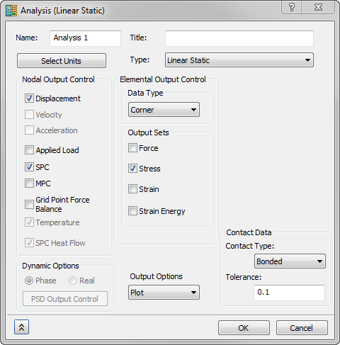
When you first start the Autodesk® Nastran® In-CAD environment, an analysis is created automatically for you. The analysis has certain default settings activated. To modify these settings, click Edit from the same panel. To create a new analysis, click New from the Analysis panel. In both cases, the Analysis dialog opens:

In this topic, we will explore the most commonly used settings in the Analysis dialog. For a description of all of the analysis settings, please see the Analysis topic in the User's Guide section.
Units
- CAD Model: The default unit system defined in Document Settings of the CAD Environment.
- SI: The MKS system (meters, kilograms, seconds, newton, kelvin and degree).
- Modified SI: The modified MKS system (millimeters, tonne, seconds, newton, kelvin and degree).
- English: The British / IPS unit system (inches, pounds seconds square per inch, seconds, pounds, Fahrenheit and degree).
- CGS: Sets the units as centimeter, grams, seconds, dyne, Celsius and degree.
Note that for models containing multiple analyses, a different unit system can be assigned to each analysis. This setting only applies to the Nastran Bulk Data file that is written out. You will not see a difference in the numbers entered in the user interface.
Type
Select the analysis from the list in the Type menu. Autodesk Nastran In-CAD supports a wide range of analysis capabilities. It is important that you understand the requirements, outputs, and limitations of a analysis type before using it for the first time. Autodesk Nastran In-CAD supports the following analysis types:
- Linear Static
- Normal Modes
- Linear Buckling
- Prestress Static
- Prestress Normal Modes
- Nonlinear Buckling
- Direct Transient Response
- Modal Transient Response
- Nonlinear Transient Response
- Direct Frequency Response
- Modal Frequency Response
- Random Response
- Multiaxial Fatigue
- Vibration Fatigue
- Linear Steady State Heat Transfer
- Nonlinear Steady State Heat Transfer
- Nonlinear Transient Heat Transfer
Nodal Output Control / Elemental Output Control
You can use the Nodal Output Control and Elemental Output Control options to control the quantities written out at the conclusion of the analysis.
For more information, please see the New Analysis topic.
Contact Data
Set the default settings for generating Automatic contacts.
- Contact Type: Select from Separation, Bonded, Sliding/No Separation, Separation/No Sliding and Offset Bonded.
- Tolerance: Specify the maximum distance between contacting entities at which automatic contacts can be generated.
|
Previous Topic: Add Contact and Symmetry Exercise |
Next Topic: Results Visualization (Post-Processing) |