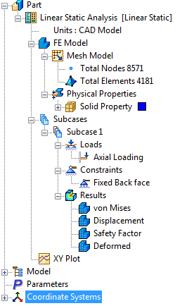
- After the solution is complete, Autodesk Nastran In-CAD places four different contour plots under Subcase 1.
- These plots have default contour template settings, located at the bottom of the tree view, under Plot Templates.
- Each of these templates can be dragged and dropped into a subcase to create a new contour plot. You can right-click the template to edit the settings.
- The tree view looks as shown below after the results are loaded:
 The
Autodesk Nastran Output window can be closed once the analysis is finished.
The
Autodesk Nastran Output window can be closed once the analysis is finished.
- Double-click on the
Displacement plot under
Subcase 1. This will display a contour of the total displacement on the deformed geometry.

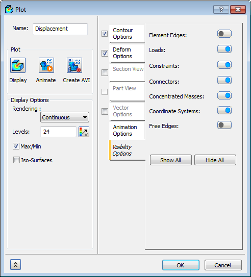
- Now right-click on
Displacement and select
Edit. Select the
Visibility Options tab, and then set the
Element Edges button to
OFF. Click
OK.
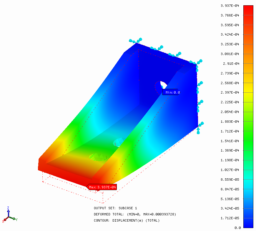
Output Description:
- On the bottom of the model area, useful information about the contour plot is displayed.
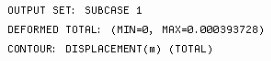
- The first line describes the output set being displayed.
- The second line gives details of the deformation vector. In this case, it is the total deformation (maximum about 0.0004m).
- The third line describes the contour being displayed. In this case, it is the total displacement. Try double-clicking on the contour plot again in the tree view. The display switches back to the undeformed mesh plot.