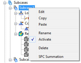
- Right-click on
Subcase 1 (or Subcase 2) and select
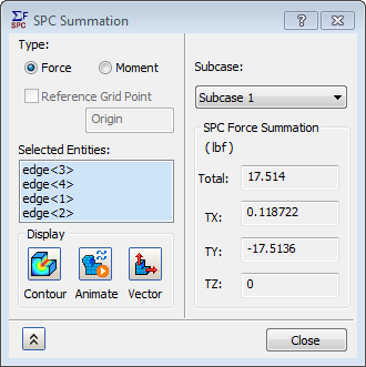
SPC Summation.
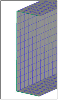
- Click the three edges where the enforced displacement loads were applied. Loads are hidden for display clarity.
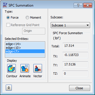
 The TOTAL is the resultant force of TX, TY, and TZ. And TX, TY, and TZ are in the global coordinate system.
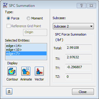
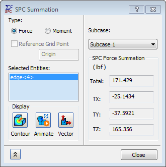
- Change the
Subcase drop-down to
Subcase 2 to see the load forces required to deflect the beam 0.025 inches in the x-direction.
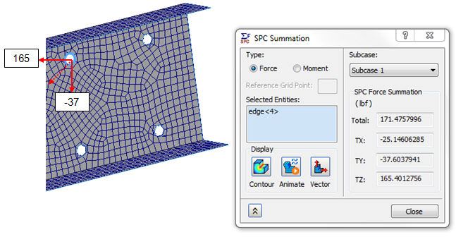
 For easy access of SPC Summation for the constraint ends, right-click on Constraints and select SPC Summation with the selection of constrained entities.
- Right-click
Fixed Holes constraint and select
SPC Summation. Make sure the
Force radio button is selected to see the
SPC Force Summation. Then select all the constrained edges listed in the
Selected Entities list.
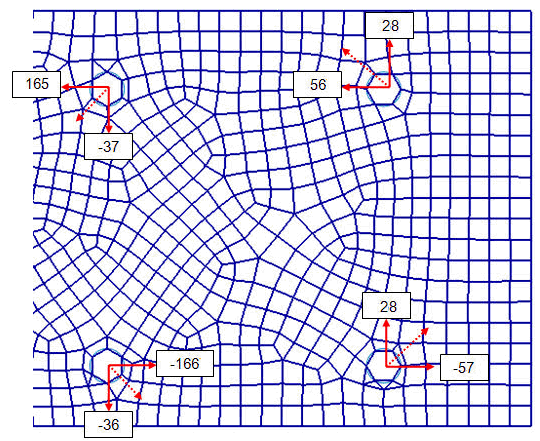
- Right-click in the
Selected Entities box and select
Clear All. Select the 1st hole as shown in the below image.
- Select
Moment radio button for
SPC Moment Summation.

- Looking at the individual reaction forces of each hole for Subcase 1 (using the methods described above), the results should be similar to what is shown below for the SPC Force Summation.
This concludes Linear Static Analysis of a Channel Using Shell Elements.
The following summarizes the main topics covered:
- Applying a shell mesh on a surface model.
- Set up a model for constraint force extraction using the SPC (Single Point Constraint) nodal output option.
- Create an enforced displacement load in two different directions with two different subcases.
- Extract constraint forces using the SPC Force Summation tool.
- Extract constraint moments using the SPC Moment Summation tool.