- In the tree view, right-click on Constraints and select New.
- Change the
Name to
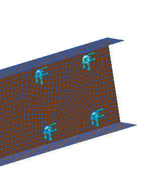
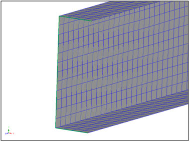
Fixed Holes and select the curves defining the holes at the right end of the beam.
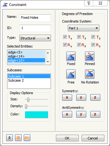
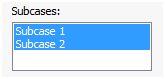
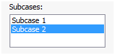
- Click both
Subcase 1 and
Subcase 2 from the
Subcases list. This will add this constraint to both subcases.
- Click on
 New button.
- Change the Name to Fix in Y Direction.
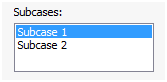
- Additionally, ensure that
Subcase 1 is selected in the
Subcases list.
- Select the three edges of the beam opposite to the side with the holes.
- Click on
 Free button and select
Ty to fix the channel in the enforced Y direction.
Free button and select
Ty to fix the channel in the enforced Y direction.
- Click on
 Duplicate button. Notice that the selection of three edges of the beam opposite to the side with the holes is retained.
- Change the Name to Fix in X Direction.
- Ensure that
Subcase 2 is selected in the
Subcases list.
- Click on
Free button and select
Tx to fix the channel in the enforced X direction.
- Click OK.
 Constrain the same nodes/surfaces/curves in the direction of the enforced displacement/rotations. It is important that only the nodes that have the enforced displacement are constrained in the direction of the displacement. All other constraints will be treated as actual boundary conditions.