The Impact Wizard facilitates drop test and projectile impact studies. Input consists simply of the direction of travel, initial velocity, and acceleration. The effective directional natural frequencies of the impactor and target in the contact state are calculated internally. The critical time step calculations are then automatically carried out based on these responses, providing a precise initial time increment and duration of the analysis. Accurate time step prediction is essential in calculating the magnitude of peak response and maintaining an energy balance during the contact event. Optional user defined time increment and duration may be specified.
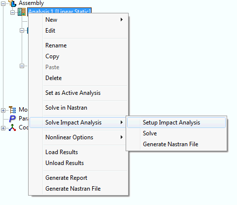
Go to the tree and right-click on Analysis; select Solve Impact Analysis-Setup Impact Analysis. The following impact analysis setup appears:
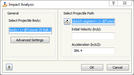
- Projectile Body: Click on the impactor body to differentiate between the impactor and the target.
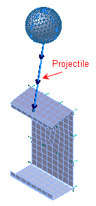
- Projectile Translation Vector: You will need to select a sketch line that defines the direction of travel of the impactor. The geometric point of the sketch line on the impactor must be located at a node. You can use Mesh Control to ensure nodes are placed in specific points/vertices/edges. Place the geometric point of the sketch line on the target at the location of the impact.
- Initial Velocity: Define your initial velocity of the impactor. The solver is going to use the initial velocity, acceleration, and the initial separation distance (or drop height) to calculate the projectile velocity at initial impact. Initial Velocity or Acceleration or both must be specified.
- Acceleration: Define your acceleration of the impactor. The solver is going to use the initial velocity, acceleration, and the initial separation distance (or drop height) to calculate the projectile velocity at initial impact. Initial Velocity or Acceleration or both must be specified.
-
Advanced Settings:
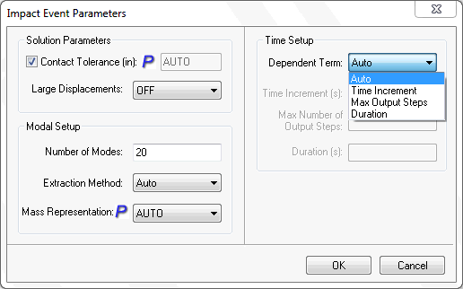
- Contact Tolerance: Specifies the contact tolerance used in automatically generating the surface contact. The value set defines the maximum normal activation distance. A recommended value is a distance approximately 10% larger than the largest gap you want to be recognized as contact. The default AUTO setting is based on the model reference dimension multiplied by 1.0E-04. For models with high levels of curvature in contact, it is recommended to explicitly define contact tolerance.
- Large Displacements: Large displacement and follower force effects and differential stiffness. Default is on.
- Number of Modes: Number of natural frequencies calculated to provide a precise time increment and duration of analysis. Default is 30 modes.
- Extraction Method: You can select either the Lanczos or Subspace eigensolver to solve for the natural frequencies. The program picks the best method based on the RAM directive setting (Parameters-Memory Management Directives) and model size.
- Mass Representation: Selecting ON requests the generation of coupled mass matrices for elements with coupled mass capability. Selecting OFF requests the generation of diagonal mass matrices. The AUTO setting will use the coupled mass formulation when rigid elements are specified in the model.
- Dependent Term: Toggles on 2 of the 3 input parameters to allow flexibility in defining the Time Setup.
- Auto: Auto will disable the Time Setup options and solver calculates the timesteps automatically based on initial velocity/acceleration and the projectile vector as distance.
- Time Increment: Time increment for impact analysis. This will override the time increment that is internally calculated.
- Duration: Duration of impact analysis. This will override the duration of analysis that is internally calculated.
- Max Number of Output Steps: Maximum number of output steps generated. Applies an override to limit the amount of response data so that the user can reevaluate the analysis feasibility. The internally calculated initial time increment will provide very high accuracy, however the total number of output time steps may be very large for a long duration, soft impact analysis.
When using the Solve option, Autodesk Nastran In-CAD solves the model using the Autodesk Nastran Solver. The progress of the analysis can be seen in the Autodesk Nastran status window that is brought up automatically on a separate tab.
When using the Solve in Editor option, Autodesk Nastran In-CAD will prompt to enter a name for the input file to save to the directory of choice. After clicking Save, the model will automatically load into Autodesk Editor to begin the analysis.