It allows you to define manual contact with different options by selecting Master and Slave entities.
When selecting the Manual option on the Surface Contact form, the following sections are available:
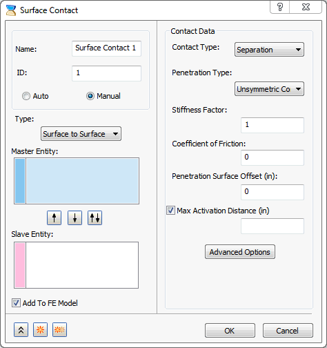
- Type: There are two methods to define surface contacts:
-
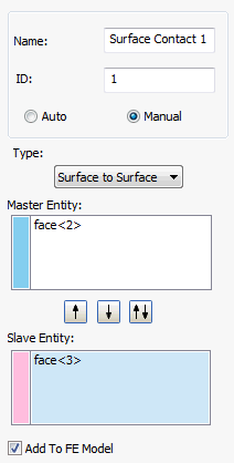
Surface to Surface:
-
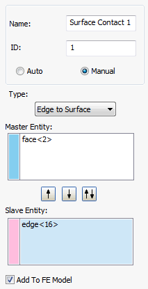
Edge to Surface:
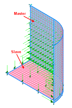
 The two faces need to be selected in order to define surface contacts i.e. Master and Slave entity in order to develop contact elements. The multiple face selection is also supported. The flip buttons are provided in order to easily shift the faces from Slave to Master and vice versa.
-
Surface to Surface:
-
Master Entity:
- This field allows you to select the master surface.
- The selection is initially set to be active in the Master Entity field.
- It allows only surface selections.
- Blue colored faces indicates that they are selected as Master entities.
-
Slave Entity:
- This field allows you to select the slave surface.
- This must be activated by clicking, once the master entities are selected.
- It allows both surface and edge selections in Surface to Surface and Edge to Surface types respectively.
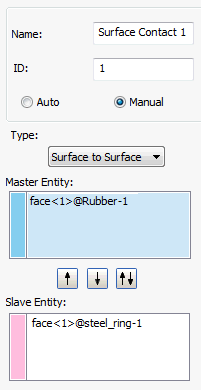
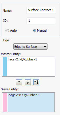
- Pink colored faces indicates that they are selected as
Slave entities.
-
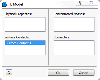
Add To FE Model: Surface contacts generated this way can be applied to an analysis by clicking the
Add to FE Model checkbox. This can also be done by dragging them onto
FE Model, or by right-clicking
FE Model, selecting
Edit, and then picking the surface contact from the list under the
Surface Contacts section.
-
Contact Data:
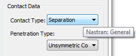
- Contact Type: In this section, different types of contact can be generated. The Contact Type terminology now matches Inventor Stress Simulation terminology. Moreover, when you hover over the Contact Type drop-down menu, tool tips are available to show the Nastran terminology, as you can see in the image below:
-
Separation
(Nastran: General)
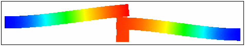
- This type of contact is a true surface to surface contact. Both sliding and opening are allowed.
- The example in the figure below shows 3 blocks, the bottom block is pushed up and free surface contact is used between the touching surfaces.
-
Bonded
(Nastran: Welded)
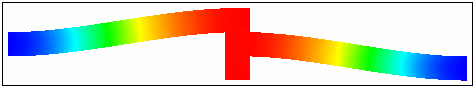
- This type of contact is used to bond the touching surfaces together. It moves together with loading.
- The advantage with this type of contact is that the mesh does not have to be the same.
- It can be useful in cases where touching surfaces on different parts have dissimilar meshes and do not undergo relative displacement. In other words the surfaces are treated to be bonded together.
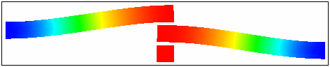
- The welded contact response between the beams is shown in the figure below. It moves together as shown in the picture.
-
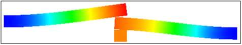
Sliding / No Separation
(Nastran: Slide)
- With this type of contact the element will act similar to a welded contact element in tension and compression, but will slide in-plane.
- Slide contact can be used in linear and nonlinear solutions.

-
Separation / No Sliding
(Nastran: Rough)
- With this type of contact the element will act similar to a general contact element in tension and compression, but will not permit sliding in-plane.
- If the analysis types are not nonlinear, the contact type will default to welded.
-
Offset Bonded
(Nastran: Offset Weld)
- The offset weld setting is intended for welded connections with significant separation between contact surfaces.
- The offset weld setting is intended for welded connections with significant separation between contact surfaces.
-
Separation
(Nastran: General)
- Penetration Type: It is applicable only for Manual contact. In this section, the type of master slave penetration can be selected. Two types are available:
-
Unsymmetric:
- In this method, only the penetration of the slave nodes into the master surface segment would be checked and adjusted.
- This may lead to master nodes penetrating into slave surface segment that can be reduced with a finer mesh.
- When some penetration of the master surface is expected, this method can be a good way to speed up the analysis. In reality there is always some degree of master slave penetration.
-
Symmetric:
- In this method, the segments of the contact pair, master and slave are also made to be slave and master respectively and both penetrations are checked and adjusted.
- More accurate results can be obtained with this method at a cost of increased computational time depending on the model size.
- In case of Edge to Surface contact, it is not applicable.
-
Unsymmetric:
- Stiffness Factor: This value controls the stiffness scaling of the contact. The stiffness is automatically determined based on the adjacent stiffness.
- The higher this value, the stiffer the contact and the less the penetration, but too high a value may cause convergence issues and chatter.
- Sometimes setting this to a lower value may help convergence, but usually the default (1.0) works well.
- Coefficient of Friction: Specify a coefficient of static friction.
- Penetration Surface Offset: Specify a penetration surface offset. This defines a numerical offset value for instances such as plate to plate or solid to plate contact.
- Max Activation Distance: This is a tolerance value that specifies the distance that contact elements should be activated. This helps limit the number of contact elements and therefore decreases solution time, prevents unnecessary and possibly conflicting contact elements. When the box is checked and no value is specified, the default solver distance will be used. This is a large distance based upon the model size. When a value is input, the solver will use that value. When the box is unchecked, the auto function will be used. Using the auto setting, the solver determines the activation distance. This is different from when the box is left blank and the default solver value is used.
- Advanced Options: Allows you to set the advanced contact parameters.
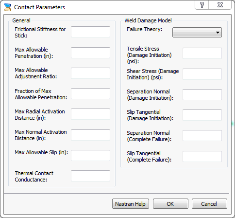
- It has two sections:
- General: It allows defining the contact parameters related to Autodesk Nastran Solver.
-
Weld Damage Model.
Refer to Autodesk Nastran Reference Manual for more information.
- It has two sections:
- Contact Type: In this section, different types of contact can be generated. The Contact Type terminology now matches Inventor Stress Simulation terminology. Moreover, when you hover over the Contact Type drop-down menu, tool tips are available to show the Nastran terminology, as you can see in the image below: