Previous: Chapter 6 | Next: Chapter 7
This exercise teaches how to launch your CAD model into Autodesk® CFD using the Design Study Manger. You will take a brief tour of the Autodesk® CFD interface and gain experience navigating your model, selecting model components, and changing object visibility.
First we should answer the questions from Chapter 2:
What do you know about this design?
- What are the operating conditions?
- A 100 m3/h (60 CFM) blower supplies 20° C (68° F) air to the car which sits in a 37° C (100° F) environment.
- What materials are used in this design?
- The car body is steel, the tires are rubber, the windows are glass, and the interior is a custom material.
What do you want to know about the performance of this design?
- What are the goals for this design?
- Uniform cooling over entire passenger body, in the front and rear seats.
- What are the success or failure criteria?
- Passenger temperatures cannot vary more than 2° C from head to toe, or more than 2° from front to rear passenger
What can you change about this design to meet your goals?
- Can the operating conditions be changed?
- Yes, but we must first study the conditions of the worst case. A smaller fan can be used, but a larger fan is not possible.
- Can materials be changed?
- No
- What parts of the design can be changed?
- Different duct locations and angles can be used.
- Duct paths may be added if they do not interfere with interior cabin space.
- Cost of changes should be minimized.
1. Open the model in CAD
The geometry files are located in the Autodesk CFD 2016 Fundamentals\<CAD> sub-folder of the folder to which you extracted the zipped model file in the "Introduction" topic . For the purposes of this exercise, we will assume that you extracted the file to the top-level C: drive.
2. Launch into Autodesk® CFD:
|
CAD |
Launch Method |
|
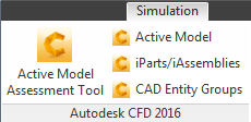
Autodesk® Inventor |
Click the Simulation tab, and select Active Model
|
|
PTC Creo and Pro/Engineer |
Open the Autodesk CFD 2016 menu, and select Launch Active Model. |
|
Solid Works |
Click the Autodesk CFD 2016 tab, and select Active Model. |
|
UGNX |
Analysis_Launch Autodesk CFD: |
3. In the Design Study Manager, assign names to the design study, design, and scenario
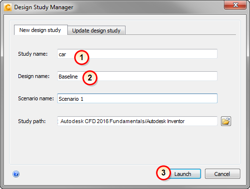
- Design study name = car
- Design name = Baseline
- Click Launch
When launching from Pro/Engineer, a prompt appears about running with interferences. Select "Yes" to proceed.
4. Close the Geometry Tools dialog by clicking the "X" in the upper right corner.
We discuss Geometry Tools in the next chapter.
5. To become familiar with navigation, practice these techniques:
- With the mouse, rotate, pan, and zoom the model.
- Zoom in and out using the mouse scroll wheel. Note that zoom is focused to the mouse curser.
- Zoom in on an area with a zoom window using mouse controls (Shift+Left Mouse Button).
- Repeat with the one-time zoom command: Navigate (panel) > Zoom (menu) > Zoom Window.
- Undo and redo zooming using Previous View and Next View (also on the Navigate panel).
- Fit the model to the window with Zoom Displayed (on the Zoom menu).
- Change model view to outline
 , transparent
  , and back to shaded
  using the Visual Style menu.
 - Use the ViewCube to examine the model from different angles:
- To reorient the model, click on corners, edges, faces of the ViewCube.
- To rotate the model in 90° increments, use the rotational arrows around the ViewCube.
For more about model navigation...
Optional Step: To set the Navigation mode to the CAD system
- Open the Application menu (button in the top left corner). Click Options.
- Click the Navigation tab
- Select the CAD system from the Navigation mode menu
- Click OK
- Exit and restart Autodesk® CFD to invoke the change. (Choose Yes when prompted to save the design study.)
- Open your design study.
- Confirm the change using the steps described above.
6. Practice selecting and deselecting objects
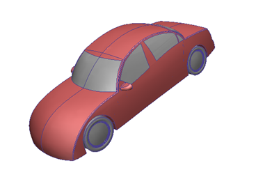
- Hover the mouse over the car. Parts turn green as the mouse moves over them.
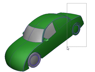
- Left click on the car body and move the mouse off of the model. The selected part turns red:
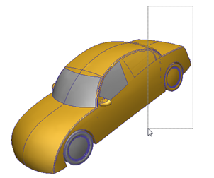
- Hover the mouse over the selected part. It turns yellow:
- Left click on the car body to deselect it.
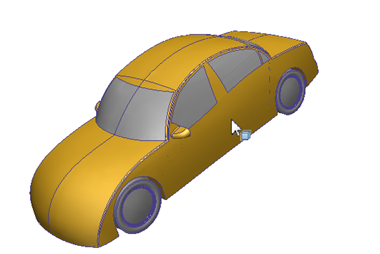
- Hold the left mouse button and drag a rectangle around the end of the car. All parts crossed by the rectangle are initially green. Release the left mouse button and they turn red to indicate they are selected:
- Deselect these parts by dragging another rectangle across them:
- Right click and choose Select all. All parts turn red.
- To deselect all parts, right click and choose Deselect all.
- To change the selection mode to surface, right click and choose Selection type > Surface.
- Practice selecting and deselecting surfaces by clicking and by dragging.
- To select all surfaces, right click and choose Select all. To deselect all entities, right click and choose Deselect all.
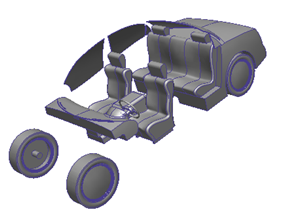
7. Practice hiding and showing objects
- To change the selection type, right click and choose Selection type > Volume.
- To hide parts, right click on a part and select Hide. Repeat with other parts.
- To resume all parts, right click and select Show all.
- To hide a part, hold the Ctrl key and middle click on the part. Repeat with other parts.
- To resume all parts, hold the Ctrl key and middle click in the graphic window (off the model).
- To undo and redo the previous steps, hold the Ctrl key and roll the scroll wheel slowly. This is useful if you accidentally hide or show a part.
- To work with surfaces, right click and select Selection type > Surface. Hide and show surfaces using these steps.
- Finish by right clicking and choosing Show all.
End of Exercise