In this step, we perform the simulation. The default analysis parameters are acceptable, but we will provide a load case description before running the analysis.
- Click the Home icon (
 ) that appears above the ViewCube when the cursor is nearby. This action will restore the default isometric view of the model.
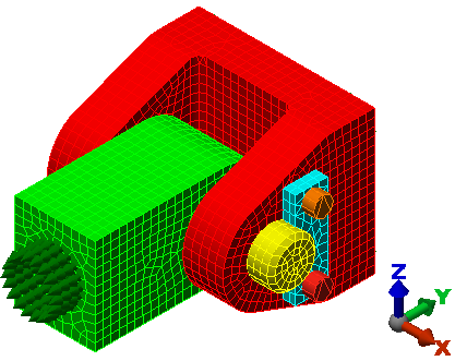
- Click Setup
 Model Setup Parameters.
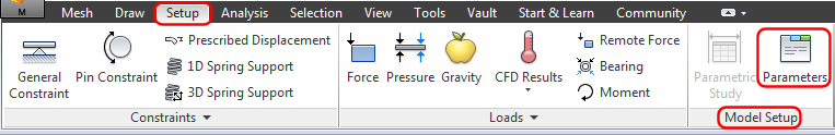
The Analysis Parameters dialog box appears, and the Multipliers tab is displayed.
- Click in the Description field for Index 1.
- Type 1,500 Pound Load.
- Click OK to accept the parameters and close the dialog box.
The dialog box should look like the following image:
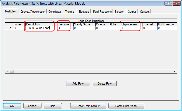 Note: The Pressure multiplier controls all surface pressure and force loads. This multiplier is 1 by default. The Displacement multiplier controls prescribed displacement loads. Since this type of load has not been applied to the model, this multiplier has no effect on the results.
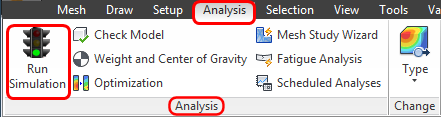
 - Click Analysis Analysis Run Simulation.
- The first time an analysis is run, the solid mesh is generated within the interior of each part. When solid meshing is complete, the solution starts. While the solution progresses, the solver log is displayed in the Details tab of the Output Bar (located at the bottom of the Simulation Mechanical window).:
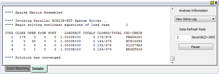
The solver iterates to determine which contact points are closed and which are open. When the solution is complete, the model displays in the Results environment with the displacement magnitude shown by default:
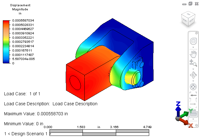
Next, we explore some results visualization tools…