- Click
 Analysis
 Analysis Run Simulation.
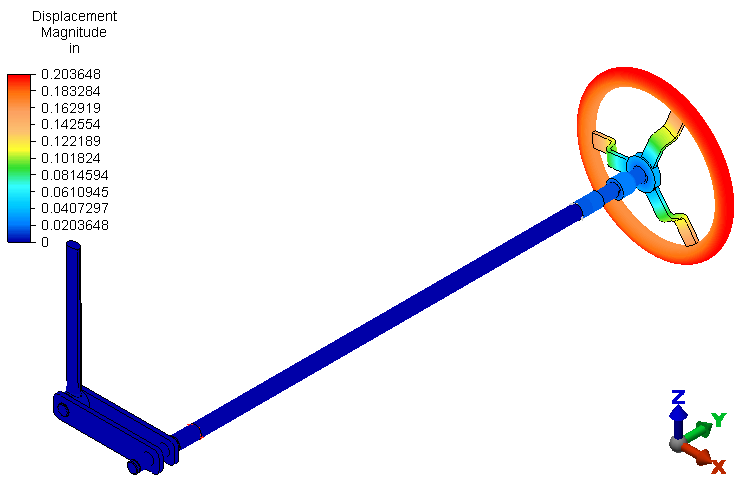
 After solid meshing, the analysis proceeds and the model displays in the Results environment. The displacement magnitude is presented initially by default. The maximum displacement is approximately 0.2 inch.
Note: 3D visualization of beam elements is enabled by default. - If the load and constraint symbols are visible, click
 Results Options View Loads and Constraints to hide them. The model should look like the following image: