- Click
 Analysis
 Analysis Run Simulation.
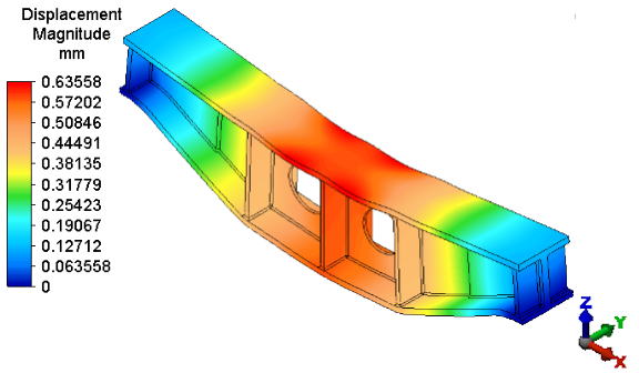
 After solid meshing, the analysis proceeds and the model displays in the Results environment. By default, the displacement magnitude is presented initially. The maximum displacement is approximately 0.64 mm, which exceeds the allowable displacement of 0.5 mm.
- If the load and constraint symbols are visible, click
 Results Options View Loads and Constraints to hide them.
 - Right-click the 2 <Boundary> heading under Parts in the browser (tree view) and deselect the Visibility option in the context menu. The 3D springs supports (boundary elements) are hidden and the model appears as shown below: