We will now apply a fixed constraint to the end of the partial link and pin constraints to the shaft extensions. One end of the shaft is help radially and axially, the other end is held only in the radial direction.
- Click
 View
View Navigate Zoom Window. Note: You can also access this command from the Navigation Bar at the right edge of the screen.
- Click and drag your mouse to draw a zoom area window enclosing only the partial link and crank, as shown in the following image:
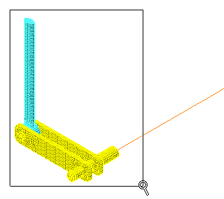
- Press Esc to terminate the Zoom Window tool.
- Click and drag your mouse to draw a zoom area window enclosing only the partial link and crank, as shown in the following image:
- With the
 Selection Shape Point or Rectangle and
  Selection Select Surfaces commands active, click the surface at the top end of the partial link, as shown below. The surface to constrain is highlighted in magenta.
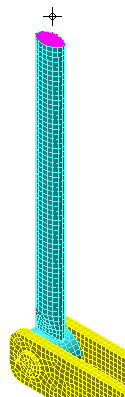
- Click
 Setup Constraints General Constraint.
 - Click the Fixed.
- Click OK.
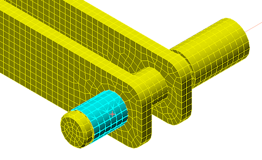
- Click the cylindrical surface of the shaft extension, between the snap ring groove and the crank arm, as shown in the following image (highlighted in cyan):
- Click
 Setup Constraints Pin Constraint.
 - Activate the Fix Radial and Fix Axial options.
- Click OK. The shaft is free to rotate about its axis because we are allowing tangential motion of the surface.
- Click the Home icon (
 ) that appears above the ViewCube when the cursor is in that area. An isometric view of the model is displayed.
 - Click View Navigate Zoom Window.
- Click and drag your mouse to draw a zoom area window enclosing only the wheel shaft extension, as shown in the following image:

- Press Esc to terminate the Zoom Window tool.
- Click and drag your mouse to draw a zoom area window enclosing only the wheel shaft extension, as shown in the following image:
- Click the cylindrical surface of the shaft extension, immediately adjacent to the hand wheel hub, as shown in the following image (highlighted in cyan):
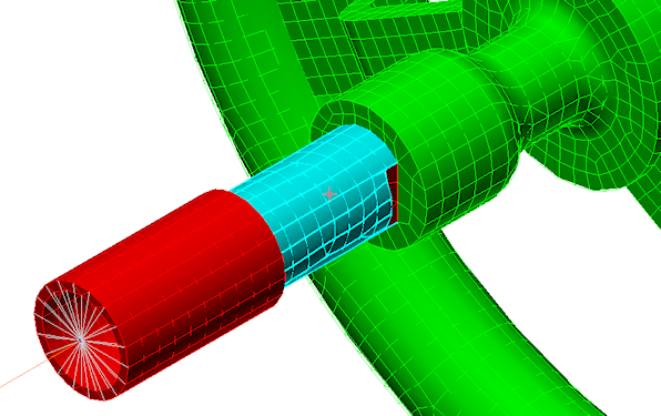
- Click Setup Constraints Pin Constraint.
- Activate the Fix Radial option.
- Click OK. The shaft is free to rotate about its axis and translate axially. The axial constraint at the opposite end (step 5a) maintains the Y-position of the assembly.