When applying a voltage, a "stiffness" value must also be specified. This is a measure of the ability of the power source to maintain the requested voltage. If appropriate, voltage sag can be simulated by specifying a limited stiffness. For example, if the stiffness is 10 A/V and the current is 5 A, the applied voltage will be reduced by a 0.5 V (5/10).
In this example, we will use an arbitrary, high stiffness value of 1x10⁸ A/V, which will result in negligible voltage sag.
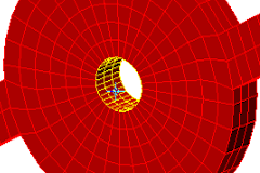
- With the cursor near the center of the motor, roll the mouse wheel to zoom in for a larger view of the hole through the center of the rotor.
- With the
 Selection
 Shape
Shape Point or Rectangle and
  Selection
 Select
 Surfaces commands active, click on the inside surface of this hole to select it, as highlighted below (yellow on red).
- Click
 Setup
Setup Loads
Loads Voltage.
 - Type 1e8 in the Stiffness field. Leave the voltage at zero.
- Click OK.
- Click
 View
View Navigate
 Orientation
 Back View.
 - Click the face of the ring at the outside diameter of the motor to select it, as highlighted below (yellow on green).

- Click
 Setup
Setup Loads
Loads Voltage.
 - Type 15 in the Magnitude field.
- Type 1e8 in the Stiffness field.
- Click OK.