We now apply 3D spring constraints to the two mounting surfaces on the underside of the beam (one at each end). The spring supports simulate an elastic foundation that is free to compress slightly under the load of the beam. Fixed constraints cause a localized, exaggerated stress at the edge of the support surfaces. In reality, we expect the maximum stress to be somewhere in the mid-span area of the support beam.
The specified 100,000 N/mm stiffness results in an insignificant displacement of the support surface under the applied load of 250,000 N. Nonetheless, the elastic-foundation effect is sufficient to alleviate the exaggerated stresses in the support area.
Note: The specified stiffness value is the spring constant at each node along the support surfaces. It is not the net stiffness of each entire surface. Therefore, the density of the mesh affects the resultant stiffness and displacement of the support surfaces.
- Click View
 Orientation Bottom View.
 - With the
 Selection Shape Point or Rectangle and
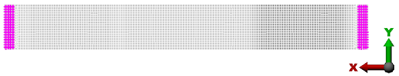
  Selection Select Surfaces commands active, click the small rectangular support surface at the left end of the beam.
 - Holding down the Ctrl key, click the small rectangular support surface at the right end of the beam. With these two surfaces selected, the model appears as shown in the following image:
- Click
 Setup Constraints 3D Spring Support.
 - Activate the X, Y, and Z checkboxes.
- Type 1e5 in the Stiffness field.
- Click OK.