Accessing the Model meshing options: Mesh Mesh 3D Mesh Settings Options. Then, click the Model icon.
When the Options button is pressed on the Model Mesh Settings screen and the Model icon is selected, two tabs appear in the dialog box—General and Mesh Matching. The Model icon is present regardless of which radio button is selected in the Mesh type section of the Model Mesh Settings dialog box.
Which options appear on the Model General tab depend on whether the option Mesh Mesh Use VCAD is activated or not. Each control described below will be identified as working with the VCAD mesher, with the legacy mesher, or both.
Mesh Use VCAD is activated, the virtual CAD mesh engine is used. When not activated, the pre-version 21 meshing routine is used. Because of the benefits of the virtual CAD mesh engine over the legacy mesh engine, the legacy mesh engine is recommended only if there is a problem with the virtual CAD mesh engine on a particular model. General tab
Default Meshing options section:
Automatically refine surface mesh: (Available only when using the legacy mesh engine.) If this check box on the General tab is activated when the model is meshed, a surface mesh will be created on the model. After the surface mesh is created, refinement points will be added depending on the geometry. The model will be meshed again with the refinement points active. If the Solid radio button is selected in the Mesh type section of the Model Mesh Settings screen, a solid mesh will then be generated.
Use automatic geometry-based mesh size function: (Available only when using the VCAD mesh engine.) This one control governs multiple aspects of the surface mesh that normally would require you to set up multiple inputs. In general, it automatically refines the mesh in the areas of curves surfaces. The particular effects are summarized in the following table.
| Activated | Not Activated |
|---|---|
| When the mesh size is set based on Percent of automatic (i.e., using the slider), a different mesh size is used for each part. The mesh size is based on the size of the individual part, the number of curves, bounding box dimensions of the part, average length of curves, and so on. | The mesh size is the same in each part, and is based on the size of the entire model. |
| Curved surfaces are meshed more finely depending on the curvature of the surface. A limit is used on the deviation between the planar element and the curved surface, and so on. | Curved surfaces are meshed based on the user-entered mesh size and refinements. |
| The mesh size is anisotropic on curved surfaces, meaning that the ratio of the element's length divided by the element's width is not forced to be near 1. For example, take a mesh size of 1-inch. The mesh in a fillet of 0.5-inch radius and 20-inches long may have elements roughly 0.25-inch by 1-inch. | The mesh size is isotropic. The element's length divided by the width is near 1. |
| The refinement settings on the Options tab of the Model Mesh Settings Surface dialog box are disabled. You cannot set the values. |
The refinement settings on are available to change. |
| In general, the default mesh size is larger. | In general, the default mesh size is smaller. |
Perform solid meshing at time of analysis (Available when using either mesh engine.) If this check box is activated and the Solid radio button is selected in the Mesh type section of the Model Mesh Settings screen, the model will not be solid meshed until the analysis is performed. This is convenient for large models that may take a significant amount of time for a solid mesh to be generated. With this option, the solid meshing time is combined with the analysis time instead of the surface meshing time.
If the Perform solid meshing at time of analysis check box is not activated, a model will be solid meshed immediately after the surface mesh is created. Deactivating the option is convenient when you plan on scheduling one or more models to run at a future time (using the scheduling options of the Solver Manager). Scheduled simulations are executed from a command window, not the user interface. In this case, solid meshing is not performed automatically at run time. So, if you do not deactivate this option, then you will have to check the model or manually execute solid mesh generation prior to the scheduled solution time.
Number of threads/cores for solid meshing: Sets the number of threads/cores on your machine that you want to use when meshing your solid model. The default value is Automatic/All.
Multi-cores are used when verifying the surface mesh and for solid meshing, while other mesh operations use a single core. Each part is meshed by one core, not split among multiple cores. Therefore, if the number of cores exceeds the number of parts, not all of the cores are used. For example, if your computer has eight cores and your model has five parts, the solid meshing process uses five cores (not all eight). Conversely, if the number of parts exceeds the number of cores, all cores are used, but all parts cannot be solid meshed concurrently.
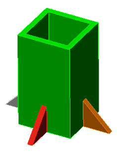
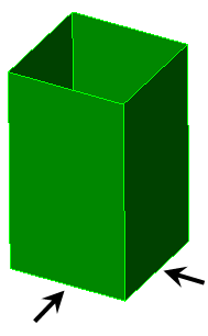
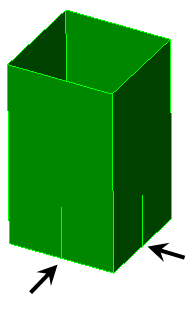
Use virtual imprinting: (Available only when using the VCAD mesh engine.) When activated, the faces of different CAD parts will be split in memory where they intersect each other, without creating additional surface numbers (that is, a virtual imprinting of one surface on another). The virtual model is used as the basis of surface mesh generation. Since the matching virtual surfaces are meshed only once, this will result in a better quality mesh. When unchecked, mesh matching is accomplished by meshing both surfaces of the parts and adjusting the mesh on one part to conform to the mesh on the other part. See Figure 1.
Tolerance: The tolerance for virtual imprinting is specified separately from the mesh matching tolerance. The tolerance field directly beneath the Use virtual imprinting checkbox is used to specify the maximum distance between surfaces and adjacent features, within which distance an intersection will be created. Increase the tolerance if valid intersections are being missed. Decrease the tolerance if unwanted intersections are being created between objects that are close but do not actually meet.
|
(a) Example solid model consisting of an assembly of multiple parts.
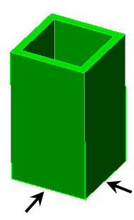
(b) Use virtual imprinting not activated. Virtual surfaces are not created at the arrows.
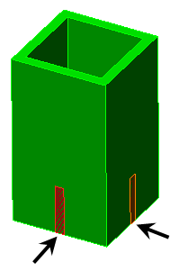
(c) Use virtual imprinting activated. The surface of the pole is split where the gussets make contact (arrowed), making a new surface in the virtual copy of the model. (New surfaces are not created in the actual model.) |
|
Figure 1: Use virtual imprinting in a Solid Model |
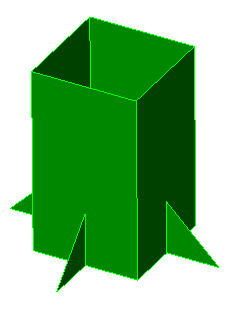
Perform imprinting within parts: This option will create virtual intersections where different surfaces within a single part meet each other. The action is similar to that of imprinting between parts. This feature is useful for CAD surface models used as a basis of plate/shell FEA models. Such models frequently use single parts comprised of several different surfaces each but without feature lines present along surfaces where an intersection with an adjacent surface occurs.
|
(a) Example plate model consisting of one part. |
|
(b) Perform imprinting within parts not activated. The virtual feature line is not created at the arrows. The mesh of the gusset may not match the mesh of the pole. |
|
(c) Perform imprinting within parts activated. The surface of the pole is split where the gussets make contact (arrowed), making a new feature line in the virtual copy of the model. The meshes will match. (New feature lines are not created in the actual model.) |
| Figure 2: Use virtual imprinting in a Plate/Shell Model |
- Note that surface splitting of the model is similar to imprinting but is a separate function. Surface splitting creates additional surfaces and feature lines in the actual model. Whereas surface splitting only works on a part-to-part basis (wherever surface areas are in common), imprinting will work on a part-to-part basis and within a single part. Imprinting can also create area, line, and point intersections. See the Surface Splitting page for details on surface splitting.
- Use virtual imprinting detects where feature lines of one surface lie on the surface of an adjacent part or surface. It does not create an intersection if the two surfaces are passing through each other (such as an interference).
- The previously discussed Tolerance value affects both part-to-part imprinting and imprinting within parts.
Retries section
This section control surface mesh retries that occur when solid meshing fails for a part. Even when surface meshing is completely successful, solid meshing can sometimes fail. When the subsequent solid meshing operation is performed and fails, the process will be retried from the surface meshing phase. The following two settings apply:
Number of retries: Set the maximum number of retry attempts that is permitted. The defaults is 6.
Retry reduction factor: The mesh size for each successive surface meshing attempt is reduced by this factor. The default is 0.75, so the mesh for each retry is 75% of the prior mesh size.
Mesh matching tab:
CAD models are not perfect. Even if the parts are drawn in perfect contact, the internal representation of the surfaces may result in adjacent surfaces that are not coincident. In other situations, parts are drawn in their as machined or stress-free condition even though the interaction of assembled parts may cause the dimensions to change. For example, the parts in a press-fit assembly are drawn with an interference. Mesh matching tolerances are used to compensate for such discrepancies. Any two nodes that are within the mesh matching tolerance will be snapped together.
On-surface tolerance based on: (Available when using either mesh engine.)
- Fraction of surface mesh size: If this option is selected, the surface mesh process will search for nodes within the radius defined by the average length of the elements (in the surrounding area) multiplied by the value in the Tolerance value field. Nodes within this radius will be snapped together. Thus, this option results in a different matching tolerance at each region of the model if the mesh size varies.
- Absolute length dimension: If this option is selected, the surface mesh process will search for nodes within the radius specified in the Tolerance value field of each node to match the meshes of coincident surfaces.
- Fraction of automatic mesh size: This option is similar to Fraction of mesh size in that the nodes are snapped if they are within a distance of the mesh size multiplied by the value in the Tolerance value field. The difference is that the mesh size is not based on the size of the elements at the area in question. Instead, the mesh size is based on the size of mesh that would result if meshed at 100% mesh size. Thus, setting a different mesh size and using refinement does not affect the tolerance dimension. However, the 100% mesh size is affected by which parts are selected for meshing.
Tolerance value: The value in this field will determine how far the surface mesh process searches for node on coincident surfaces to match the meshes. The meaning of this value, whether it is a dimension with units of length or a multiplier, depends on the option selected in the On-surface tolerance based on drop-down box.
Do not match the mesh of contact pairs when applicable: (Available only when using the VCAD mesh engine.) This option is used to not force the meshes to match between two touching surfaces. Since the mesh will not match, the parts will not be connected together. (Note that the mesh may still be the same size and therefore matched if the surface areas are identical.) This option is used only in these situations:
- When the analysis is set to use smart bonding (see the Types of Contact page).
- Mechanical Event Simulation (MES) and nonlinear stress when surface to surface contact is defined between the two surfaces. (The nonlinear contact solution is more stable, and the analysis runs faster, when the meshes are not matched along contacting surfaces.)
In other analysis types, setting the contact type to Free will accomplish the same goal since the parts will be able to separate.
- For the Do not match the mesh of contact pairs when applicableoption to work, define the applicable contact type before meshing the model. If the applicable contact type is defined after the model is meshed, the model should be remeshed to not force the matching of nodes.
- There are some points where the mesh has to align. Imagine two cubes of the same size in contact. Since the four corners are at the same location, these nodes will match. The rest of the mesh will not be forced to match. Although the four corners match, separate nodes will be created when the model is analyzed.
- In MES, do not use the Do not match the mesh of contact pairs when applicable if using the Point to Point contact type. Point to Point contact requires the meshes to match (unlike the other contact types, which are based on contact between a node on one part and an element face on the other part).