Different types of issues can occur with the connection between adjacent parts. One issue is that the nodes might not be connected together as intended or desired. When parts comprised of two different element types are connected, the element type with the fewest degrees of freedom (DOF) at each node dictates the behavior of the connection. For example, elements with no rotational DOF (such as bricks and tetrahedra) cannot resist moments. So, these connections have no rotational stiffness. The supported nodal degrees of freedom dictate what type of load is transmitted between the parts. This page discusses a couple of these issues and provides methods for producing the desired connection characteristics.
Bonded Contact Between Plates and Bricks:
The issue here is related to the fact that the degrees of freedom for each part are different. Bricks have only the three translational degrees of freedom (Tx, Ty, and Tz) while plates (and shells) have all DOF except for rotation about the direction normal to the element. Therefore, the bricks cannot apply a moment to the plates to prevent the plates from rotating. Without special considerations, a connection between plates and bricks along a straight line of nodes will result in a hinge. This is depicted in Figure 1. In the case of linear static stress, hinge connections frequently result in a model that is not statically stable, though the example pictured below is stable due to the constraint at the opposite end of the plate.
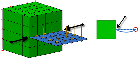
Figure 1 Hinged Combination of Bricks and Plates
The black arrows represent the hinge line. The schematic on the right shows a side view and how the plate deflects; note the rotation at the hinge line. If the free end of the plate was not supported, the plates is free to rotate around the hinge line which would result in a statically unstable configuration.
To avoid this hinge effect, the bonded contact between the plate and brick needs to be distributed over an area; specifically, at least three nodes not in a straight line. See Figure 2.
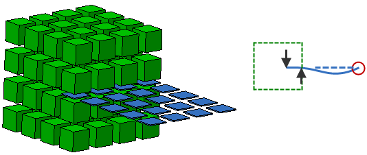
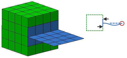
Figure 2 Statically Stable Combination of Bricks and Plates
In the top method, the plate is embedded one element deep into the bricks. (The elements are shrunk to show the space between them.) This method is applicable to hand-built (structured mesh) models. In the bottom method, a tee connection of plates is created on the surface of the bricks. In the schematics on the right, which show the side view, the arrows represent the reactions at the brick/plate interface. (These are in fact the forces that are transmitted between the nodes of the bricks and plates.) Since force couples can resist moment loads, the plate is now statically stable.
Bonded Contact Between Bricks and Beams:
The connection between beams and bricks has a problem similar to the plate-to-brick connection: the bricks cannot prevent the beams from rotating. Beams support all six degrees of freedom (three translations and three rotations), but the bricks only support the three translational DOF (Tx, Ty, and Tz). The solution is likewise similar to plate/beam connections: make a web of beams (or spokes) to connect to the bricks. The beams must connect to the bricks at three or more points, not in a straight line, to form a statically stable solution. A beam attached to a brick at a single point acts like a ball joint, which typically results in statically unstable models. Figure 3 shows an example.
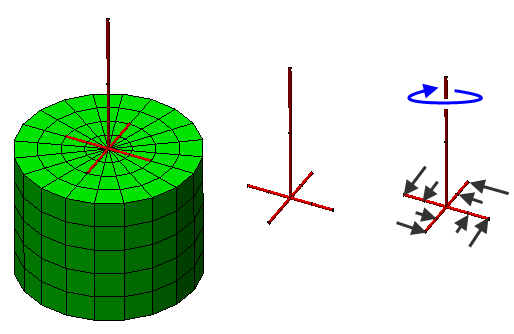
Figure 3 Statically Stable Combination of Bricks and Beams
The left side of the figure shows the beams and bricks together; the middle shows the beams only. Note how the vertical member is connected to four other beams that tie to the bricks at multiple points. If a torque were applied to the beams, such as in the schematic on the right side, then the black arrows represent the reactions provided by the bricks.
 Create Remote Load. If working with a CAD model, use Draw Design Centroid Creator to create a construction vertex at the centroid of the surface. See the Remote Loads and Constraints and Add Geometry pages, respectively.
 Bonded Contact Between Plates and Beams:
There are two situations to consider when combining plates with beams.
- A plate cannot resist the moment about the axis normal to its face. Therefore, if you attach a beam normal to a plate, the plate element will not be able to keep it from rotating. To avoid this, it is recommended to add beams (spokes) from the end of the normal beam to a few other nodes in the plate to form a statically stable model. The method is the same as for beam/brick connections, as shown in Figure 3.
- If you model a beam lying on a plate, you must remember that you are drawing the midplane of the plate elements and the neutral axis of the beam elements. Therefore, if you draw beam part along the plate, you are really saying that the neutral axis of the beam lies along the midplane of the plate. This is most likely not accurate. There are two possible ways to model this situation correctly within the FEA Editor environment.
- You can draw the neutral axis of the beam and the midplane of the plate where they actually exist and connect them in several places with effectively rigid beams.
- You can draw the neutral axis of the beam along the midplane of the plate. Then, using Selection Select Lines, select the beam elements. Right-click in the display area and select Add Beam Offset from the context menu (or click the Setup Beam Loads Beam Offset ribbon command). Specify the distance and direction between where the beam is drawn and where the neutral axis is actually located. For example, if an 8 inch high wide flange beam is connected along a 0.5 inch thick plate, the offset distance would be 4.25 inches in the appropriate direction (half the plate thickness plus half the beam height).