The controls in the Linearization Controls section are used to define the Stress Classification Line (SCL) for your model.
What is a Stress Classification Line (SCL)?
- A stress classification line is a straight line that extends from free surface to free surface of a material. In other words, a stress classification line is typically drawn across the thickness of a given section of a solid. In the general case, the ends of this line do not have to coincide with FEA nodes.
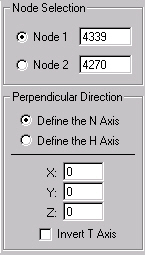
Node #1: In this field enter the node that will be the first end point of your SCL. If you activate the radio button beside Node 1, you will be able to right-click a node in the Display Area to select a node graphically. You can perform an Inquire: Nodes and Boundary Conditions: Get command in the Results environment to determine the node number of a particular node.
Node #2: In this field enter the node that will be the second end point of your SCL. If you activate the radio button beside Node 2, you will be able to right-click a node in the Display Area to select a node graphically. You can perform an Inquire: Nodes and Boundary Conditions: Get command in the Results environment to determine the node number of a particular node.
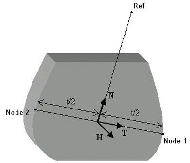
Perpendicular Direction Section: The stress values along the SCL will be reported as six stress tensors. Therefore you need to define the three perpendicular directions that these tensors will be calculated along. These axes are named the T, N, and H axes. The T axis is defined by the SCL.
- If the Define the N Axis option is selected, a line perpendicular to the T axis passing through the Reference point (designated as Ref in the Display Area) will define the N axis. The H axis will be defined as the axis perpendicular to both the T and N axes.
- If the Define the H Axis option is selected, a line perpendicular to the T axis passing through the Reference point (designated as Ref in the Display Area) will define the H axis. The N axis will be defined as the axis perpendicular to both the T and H axes.
- The Reference point will be defined in the X, Y, and Z fields below the Define the N Axis and Define the H Axis options.
- You can use the Invert T Axis option to reverse the direction of the positive T axis.
The figure below shows the local axis configuration if the Define the N Axis option is selected.