Technical info about the layering shaders
Some technical details
Light Path Expressions (LPE) supported
In this version of the layering shaders, the passes available have the following LPE description. Note that the closest typical pass name follows it in the third column.
| LPE | descriptive name | typical pass name |
| "L<RD>E" | "direct_diffuse" (reflection) | "diffuse" |
| "L<R[GS]>E" | "direct_glossy_specular" | "specular"/"highlight" |
| "L<RG>E" | "direct_glossy" | "specular"/"highlight", glossy part |
| "L<RS>E" | "direct_specular" | "specular"/"highlight", specular part |
| "L.+<RD>E" | "indirect_diffuse" | "indirect" |
| "L.+<R[GS]>E" | "indirect_glossy_specular" | "reflection" |
| "L.+<RG>E" | "indirect_glossy" | "reflection", glossy part |
| "L.+<RS>E" | "indirect_specular" | "reflection", specular part |
| "L.+<TD>E" | "diffuse_transmission" | "translucency" |
| "L.+<T[GS]>E" | "indirect_glossy_specular_transmission" | refraction" |
| "L.+<TG>E" | "glossy_transmission" | refraction", glossy part |
| "L.+<TS>E" | "specular_transmission" | "refraction", specular part |
| "<L'front'>.*TV[VR]*TE" | "front_scatter" | |
| "<L'back'>.*TV[VR]*TE" | "back_scatter" | |
| "L.*VE" | |
| "LaE" | "emission" | |
| "La<RS>E" | | |
| | "debug_highlight" |
| | "debug_reflection" |
| "L<RD><TS>+E" | "direct_diffuse_transmitted" |
| "L<RG><TS>+E" | "direct_glossy_transmitted" |
| "L<RS><TS>+E" | "direct_specular_transmitted" |
| "L.+<RD><TS>+E" | "indirect_diffuse_transmitted" |
| "L.+<RG><TS>+E" | "indirect_glossy_transmitted" |
| "L.+<RS><TS>+E" | "indirect_specular_transmitted" |
This LPE name may be used exactly as is with the LPE attribute on a framebuffer, or through string options, an alternate descriptive name for any of the above given LPE names can be arbitrarily assigned. If one does not specify by an LPE name, the above descriptive names can be used directly as framebuffer names. This means that any user framebuffer named the descriptive name above will be written automatically by the layering components.
About mila_glossy_reflection and "mila use visible area highlight"/"mila visible area highlight"
Glossy/Specular highlights (directly visible lights through reflective surfaces) have been a trick in computer graphics when using traditional light loops. In reality, they are a reflection of the light source. But for this to occur in computer graphics with traced reflection rays, the light source must be an area light, ie, not an infinitessimal point, and also set to be visible in the scene. Rendering implmentations that do or do not use light loops can easily confuse terms for users in how to specify what they are used to using. This string options allows defining this more clearly to all the glossy shaders.
Note
The "mila use visible area highlight" on/off enables or disables use of the feature. The "mila visible area highlight" string option has a default of -1 which means automatic.
In most cases you leave it at that and forget about it.
Here is the logic applied to the option:
Area lights set not to be visible always generate specular highlights, as do any non area lights. This is the same behavior as mia_material has.
The "mila visible area highlight" string option is an extension of the old mia_materials parameter no_visible_area_hl, which ONLY turned specular highlights on/off for visible area lights, and did not change visible area lights reflections in any way.
In contrast, this parameter is actually a proper balancing tool between actual reflections of visible area lights, or doing specular highlights of said lights.
- -1
- (the default, and recommended) an automatic heuristic is used to determine the value depending on glossiness.
- 0.0
- visible area lights generate no specular highlights but are instead 100% visible in reflections. This is good for high-glossiness or specular surfaces, and for large area lights (any time the area light covers a larger subtended angle than the glossy cone).
- 1.0
- visible area lights generate traditional specular highlights, and are not visible to reflection rays. This is good for surfaces with a low glossiness and where area lights are small.
- 0.0 > x > 1.0
- any value greater than 0.0 but less than 1.0 is a blend between the two kinds of reflections. They are still kept in balance so the total energy is accurate.
Examples
Here are some example images to illustrate the problem caused by sampling visible areas in the two different ways. These images are intentionally rendered with low setting to clearly drive home the issues with grain in the two cases:
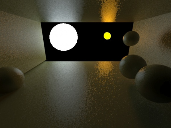
"mila visible area highlight" = 0.0 for a low glossiness surface. This means all sampling is done in reflection rays, but since the spread of the glossy cone covers much larger area than the lights, this causes heavy grain (especially for the smaller light, which surface must have a higher radiance to emit the same total intensity)
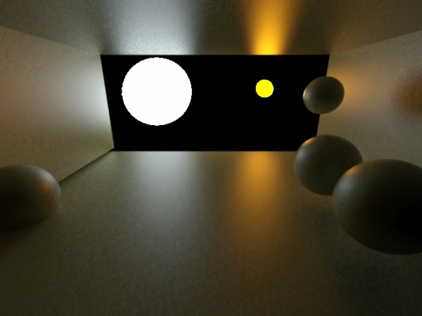
"mila visible area highlight" = 1.0 for a low glossiness surface. In this case, all sampling is done from the light, reducing the grain very much, because the probability of light samples ending up inside the glossy cone is high
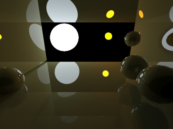
"mila visible area highlight" = 0.0 for a high gloss (specular) surface. All sampling is done by reflection rays, but since the glossy cone (in this case a single ray) is so much smaller than the area of the light, this now gives a clear reflection
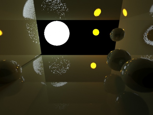
"mila visible area highlight" = 1.0 for a high gloss (specular) surface. In contrast, attempting to use light samples for the specular cases gives a very low probability that the light sample will even exist within the very narrow cone of the specularity, causing noise from THAT instead
As we can see, high gloss and low gloss surfaces have different "good" settings for the "mila visible area highlight" parameter. For this reason, a heuristic setting "-1" exists, which computes the actual value used based on the glossiness. This is useful together with variable glossiness:
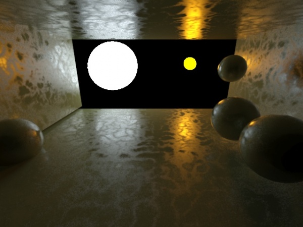
"mila visible area highlight" = -1.0 for a variable-glossiness surface. This mode attempts a best setting depending on the glossiness, to get the best possible image


