Now we will look at the preview of the model in PV/Designer and then generate the model and view it in the FEA Editor environment.
- Click the middle mouse button in the display area and drag the mouse to rotate the viewpoint of the model. Inspect the structured mesh of the pressure vessel.
- Click
 View
View Orientation Isometric to return to the isometric view. The model displays as shown in the following image.
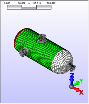
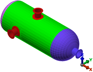
- Click File Done to exit PV/Designer and open the model in the FEA Editor environment of Simulation Mechanical. The model displays as shown in the following image. The element type has been set automatically to Plate for all parts.
Many options are available for the shape of the heads, offsetting the position and angle of nozzles, placing heads on nozzles, making the nozzles tapered, and more. For this tutorial, we used automatic mesh divisions. Manual mesh customizations are also possible. Finally, PV/Designer can output plate/shell or solid geometry.
Note: Once the model has been transferred to the FEA Editor environment, you can return to PV/Designer to modify the geometry or mesh by clicking  Tools Edit Pressure Vessel.
Tools Edit Pressure Vessel. This tutorial is now complete.