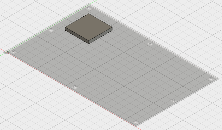
Add the chip to top of the circuit board and then position it at the specified distances from the board edges. Initially, create the chip so that its uppermost corner is coincident with the uppermost corner of the board (as oriented in the Home view). Then, move it 1.0 inch away from both the short and long edges of the board.
- Position the cursor over the Chip:1 heading in the browser. A circle (radio button) appears at the right side of the heading. Click this Activate Component radio button to make the chip the currently active component. In the next few steps, we add geometry to this part.
- Click
 CREATE
 Box.
Box. - Click on the top surface of the board to choose the drawing plane for the base rectangle.
- Click the uppermost corner of the board (as displayed in the Home view).
- Drag the mouse towards the opposite corner of the board to start a rectangle. One of the two dimensions is highlighted and the model appears2 as shown below. Since the chip is square (2 inch x 2 inch), the order that the two dimensions are specified does not matter.
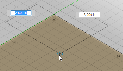
- Type 2 and press Enter to lock in the first dimension. The other dimension field will then be highlighted.
- Type 2 and press Enter to lock in the second dimension.
- Press Enter to accept the rectangle.
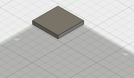
- In the BOX dialog box, type 0.25 in the Height field.
- Press Enter (or click OK) to complete the command and create the chip. The model should look like the following image:
- Click the Chip:1 heading in the browser to select this part. Both the heading and the part itself are highlighted in blue to indicate that the part is selected.
- Click
 MODIFY Move. The MOVE dialog box appears.
 - Type 1 in the X Distance field.
- Type -1 in the Y Distance field.
- Press Enter (or click OK) to complete the Move command. The model should look like the following image:
- Click
- In the QAT, click
 Save.
Save.