Create a solid model of the circuit board assembly shown below using Autodesk SimStudio Tools. All dimensions are in inches:
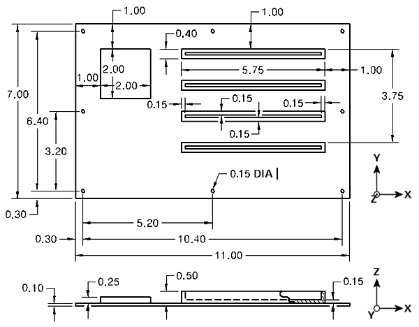
- The assembly consists of six parts—the board, the chip, and four edge connectors.
- A single hole is placed at a corner of the board and the remaining holes are created by specifying a 3x3 rectangular pattern. One extraneous hole at the center of the board is omitted from the 3x3 pattern, leaving only the eight holes shown in the above diagram.
- The Shell command is used to hollow out the edge connectors, leaving a wall thickness of 0.15 inch for the four sides and the bottom. The resulting slots are 5.45 long x 0.1 wide x 0.35 deep.
- Use the default material properties in SimStudio Tools for all three parts. We define the actual thermal properties of the material within Autodesk Simulation Mechanical during the subsequent steady-state and transient heat transfer analysis tutorials.