This topic shows how to use Max Creation Graph (MCG) to design a simple graph that produces an icosahedron.
- Start 3ds Max, open the Scripting menu, and choose Max Creation Graph Editor.
The Max Creation Graph editor dialog opens. It consists of a menu bar and four windows: Available Nodes/Operators, Operator Description, Message Log, and the main graph window, currently with a single tab labeled "Untitled."
- In the Operator Nodes list, scroll down, if necessary, to the Geometry - TriMesh item and click the arrow button to its left to expand the category.
- In the Geometry - TriMesh list, scroll down to the Icosahedron item. Drag the Icosahedron item out into the graph editor window.
This creates an instance of the Icosahedron node in the editor window.
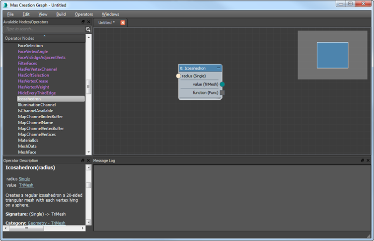
This node contains the basic functionality for creating an icosahedron object. Note that it has an input connector on the left side, labeled "radius (Single)," and on the right side an output connector, labeled "value (TriMesh)." (The function connector isn't used in this procedure.) As you can see, the logic flows from left to right. This is true of all MCG graphs.
As indicated by the labels, the node's input requires a single-precision floating-point decimal value, and the output requires a node that produces a triangle-based mesh object.
Note: MCG provides two different types of input nodes:- Input nodes let the graph author specify an input value within the graph. This is most useful when you know what the input value will be, and that it probably won't change.
- Parameter nodes let the user of the graph provide the input value. This type of node is more elaborate, letting you specify minimum, maximum, and default values, and the label of the input request in the software interface.
To complete the graph, you'll add and connect a parameter node that lets the user of your graph provide a value for the Radius parameter, and an output node to produce the geometry.
- In the Geometry - TriMesh list, scroll down to the Icosahedron item. Drag the Icosahedron item out into the graph editor window.
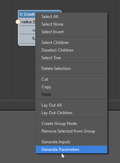
- In the graph editor window, select the node, if necessary, and then right-click it. At the bottom of the menu that opens, choose Generate Parameters.
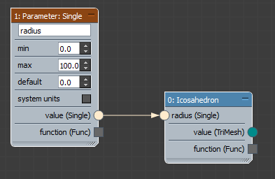
A Parameter: Single node appears in the editor window, already wired to the Icosahedron node's input connector. This is a handy shortcut for finding the Parameter: Single node, dragging it into the window, and then manually wiring it to the input connector.
In the next step, you'll use a different shortcut for finding a node whose name or type you already know.
- Click anywhere in the editor window, then on the keyboard type "x".
A search window opens with a list of all nodes. Because you need an output node, you have a pretty good idea what to search for.
- Type "ou".
That's all you need to find matches with all nodes whose names begin with "Output." The list now shows only the five nodes that match this search criterion. Considering that this graph will create a geometry object, the choice is obvious.
- Click the "Output: geometry" item in the search list.
The node is added to the graph editor window.
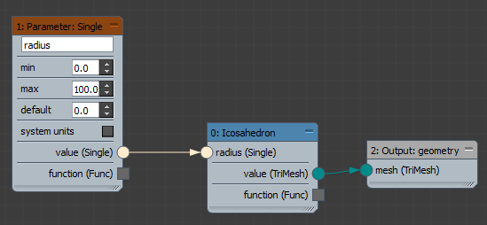
- Drag the Output: geometry node to the right of the Icosahedron node, if necessary, and then drag between the Value (TriMesh) output connector of the Icosahedron node and the Mesh (TriMesh) input connector of the Output node. The direction doesn't matter.
The result is a color-coded wire between the two connectors.
- Open the File menu, choose Save, and save the graph as Icosahedron.maxtool. Note: The Message Log window tells you that validation succeeded for the graph, that the corresponding MAXScript file was successfully generated, and the .maxtool file was saved as well.
Validation shows that there are no major problems with the graph. To use its output, however, it's necessary to evaluate it.
- Open the Build menu and choose the Evaluate command.
The Message Log window now shows additional statements to the general effect that all is well.
Next you'll use the graph to create an icosahedron in the scene.
- On the Create panel of the main 3ds Max interface, make sure the Geometry button is active (
 ). Then open the drop-down list just below the button and choose Max Creation Graph.
 On the Object Type rollout, the Icosahedron button appears.
- Click the Icosahedron button, then click once in any viewport.
The axis tripod appears where you clicked, but no object appears. If you look at the Parameters rollout, you can see why: The object has a radius of 0.0.
- Increase the radius to 12.0 or so.
Now you can see the icosahedron geometry. This is regular polygonal geometry, like most other objects in 3ds Max. You can use it in any normal way: Convert it to an editable format, apply modifiers and materials, and render it.
This new object type has become a part of your 3ds Max installation and will be available from now on. For more information about setting default values, transferring your objects to fellow 3ds Max users, and so on, proceed to the remaining lessons in this section.