Determine the progression of individual ply failures and the associated progressive laminate stiffness degradation as a result of applied loads.
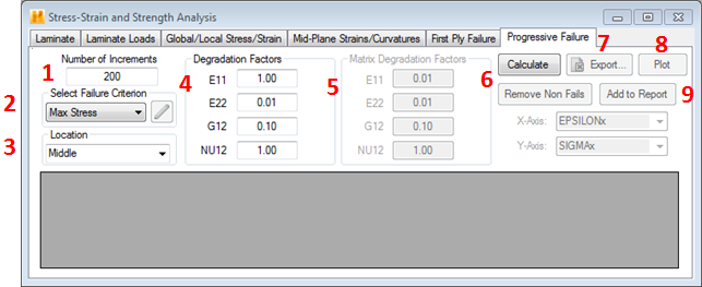
To perform a Progressive Failure analysis of a laminate, select the Progressive Failure tab within the Stress-Strain and Strength Analysis window, found under the Laminate drop-down menu.

- Number of Load Increments - Define the number of load increments (default = 200) to be used in the Progressive Failure analysis.
- Failure Criterion - Select the failure criterion to be used in the Progressive Failure analysis by choosing from among the seven failure criteria available under the 'Select Failure Criterion' drop-down menu. (See Appendix C for details on available failure criteria.) If the selected failure criterion requires the specification of additional parameters, the
 parameters button will become active. In this case, click the button to define the required parameters before proceeding.
 - Location for Failure Evaluation - Identify the location (top, middle, bottom) within each ply where the failure criterion will be evaluated (default = middle).
- Degradation Factors / Fiber Degradation Factors - Specify degradation factors for the various properties (E11, E22, G12, and/or NU12) of any lamina that experiences a failure. A value of 1.0 assigned to a lamina property means the property retains it full original value after the lamina fails. A value of 0.01 assigned to a lamina property means the property will be reduced to 1% of its original value after the lamina fails.
If the failure criterion chosen is MCT, this option becomes Fiber Degradation Factors and you can specify these values for the fiber constituent only. When MCT predicts a fiber failure, the fiber and matrix properties are degraded using the supplied values from the Fiber Degradation Factors and the Matrix Degradation Factors, respectively. A new composite stiffness will be calculated via micromechanics using the reduced properties.
- Matrix Degradation Factors - This option is only applicable to analyses utilizing the MCT failure criterion. You can specify the degradation factors for the matrix constituent of the composite. When MCT predicts a matrix failure, the matrix properties are degraded using the supplied values (while the fiber properties are kept at an undamaged state) and a new composite stiffness is calculated via micromechanics.
- Calculate/Remove Non Fails - After you have finished modifying the analysis control parameters, the Progressive Failure analysis is initiated by clicking the Calculate button. This displays the results in tabulated form. Select the Remove Non Fails button to display a tabulated list of only failed plies.
- Export - After the results have been computed and displayed, click Export to write the results to a *.csv file compatible with Microsoft Excel.
- Plot - After the analysis is completed, you can request that results be displayed in a 2-D graph by clicking the Plot button.
- X-Axis (Identify Strain Component) - Select the strain component that will be plotted on the horizontal axis of the progressive failure plot. Available choices include εx, εy, εxy .
- Y-Axis (Identify Stress Component) - Select the stress component that will be plotted on the vertical axis of the progressive failure plot. Available choices include σx, σy, σxy.
- Add to Report - After performing the analysis, you may add the results to a report.
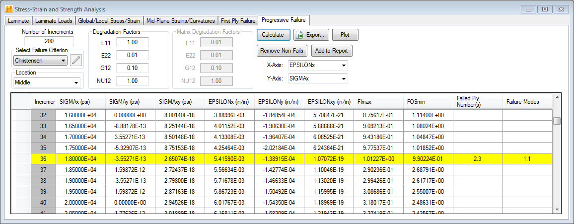
An example of the results generated in a Progressive Failure analysis is shown below.

In the image above, we have scrolled down the list of load increments to expose load increments 32 through 40. Note, the data line for any particular load increment lists the volume averaged laminate stresses (σxx, σyy, σxy), the volume averaged laminate strains (εxx, εyy, εxy), and the largest ply failure index in the laminate. The averaged stresses and strains for a laminate can be found using the equations below.


- The row of data is highlighted for any load increment that resulted in the failure of one or more plies. For example, the image above shows load increment 36 as highlighted since it resulted in the failure of a material ply.
- The newly failed plies are listed in the Failed Ply Number(s) column for the load increment in question.
- The failure mode of the failed ply is listed in the Failure Mode column for the load increment in question. (See Appendix C for the definition of the failure mode for each available failure criteria.)
- Remove Non Fails - You have the option to filter the results so that only the load increments where ply failures occurred are displayed. An example of this is shown in the image below.

- Export - You have the option to print the Progressive Failure results to a *.csv file compatible with Microsoft Excel by clicking the Export button.
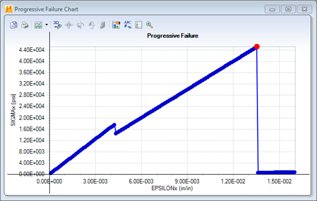
- Plot - Note the following when plotting:
- Plotting with the Remove Non Fails filter invoked will only plot the failed points.
- When the last ply in the laminate has failed, mark this as the laminate's ultimate strength. All other data points plotted after this ultimate strength should be neglected. An example of this is shown below where the failed plies of a random laminate are shown. Here, it is indicated that the ultimate axial strength of the laminate is 4.40E+04 psi. A plot of the failure analysis is shown in the plot below. The data point highlighted in red corresponds to the predicted ultimate strength of the laminate and therefore all data points plotted beyond this should be neglected.
