The Set-up Parameters tab is used to define the bolted connection. This includes the number of plates, the materials, and the bolt spacing.
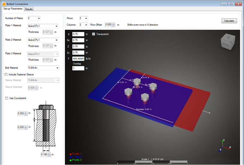
Number of Plates
Select the number of plates that make up the laminated joint. You may specify 2 or 3 plates. The graphic of the bolted connection will update automatically to indicate the number of plates specified.

Materials
Choose the laminates that define each plate and select the metal material the bolt is made of.
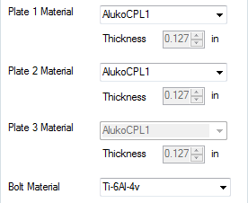
- Plate Materials - You must select a composite laminate for each plate in the joint. The thickness shown for each plate is calculated from the laminate definition. Refer to the Creating a New Laminate page to create a laminate for one (or more) of your plates. Each plate in the bolted connection may use a different laminate.
- Bolt Material - Select a metal from the drop-down menu to define the bolt material. To create a new metal, refer to the Create a New Metal page.
Bolt Spacing
Control the bolt pattern by specifying the number of rows and columns of bolts, the spacing between bolts, the distance to the edge of the plate, and a row offset.
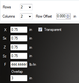
- Rows - Select the number of rows of bolts that define the joint (1-5)
- Columns - Select the number of columns of bolts that define the joint (1-5)
- X - Distance from the edge of the plate to the center of the bolt along the x-axis
- Sx - Spacing between bolts (center-to-center) along the x-axis
- Z - Distance from the edge of the plate to the center of the bolt along the z-axis
- Sz - Spacing between bolts (center-to-center) along the z-axis
- Overlap - The length of the connection that is shared by each plate
- Row Offset - Shift the even numbered rows of bolts along the x-axis
Fastener Sleeve
Include the use of a fastener sleeve by clicking the checkbox. If you include the fastener sleeve, you must specify the sleeve material and diameter.

Bolt Geometry
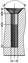
Define the bolt geometry, including the length of the shank, the length of the threads, and the bolt diameter. It is good practice to ensure the threads of the bolt extend beyond the bottom of the plates.
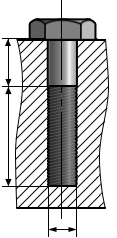
You may select to use a countersink. If you do so, you must specify the depth of the bolt head.
Apply a Load
Specify the load applied to the bolted joint. The load is entered in the box labeled F and is specified as a force per unit length. For example, if a load of 100 pounds is to be applied to a connection with a plate width of 4 inches, the load should be entered as 25 lb/in (100/4 = 25).
Calculate
After the bolted connection has been defined, click Calculate in the top right corner to analyze the joint. Move to the Results tab to view the results of the analysis.
There is a known display issue for DPI settings greater than the default 100%. Click here for more details.