Add a new laminate to the material database.
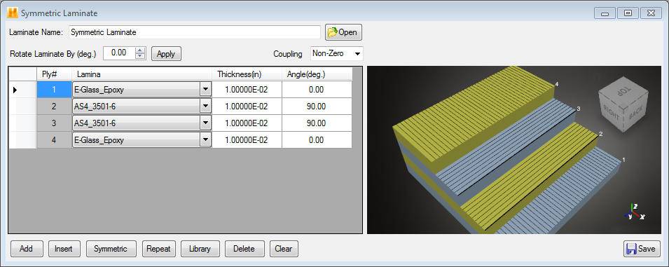
Selecting a New Laminate from the New Item drop-down menu opens the New Laminate window as shown below.

- Laminate Name - The name of the new laminate must be specified by typing in the box labeled Laminate Name. If Use Most Recent Laminate is checked under Preferences, the window will be populated with the laminate most recently used in a session.
- Rotate Laminate By (deg.) - This option rotates all plies in the laminate by a specified angle that must be in the range of -90° to 90°. The default value of the laminate rotation angle is zero. The laminate rotation is performed about the global Z axis (right-hand rule positive). After specifying a nonzero laminate rotation angle, click Apply to perform the rotation. Note, the laminate rotation angle is only performed on plies that have already been defined and appear in the display window. After performing a laminate rotation, any new plies added to the laminate are not subjected to the previously imposed laminate rotation.
- Coupling - When the Coupling option is set to "Zero", the laminate is forced to behave as if it was a balanced, symmetric laminate by explicitly zeroing the entire [B] matrix, along with the shear/extension coupling terms of the [A] matrix. This process effectively eliminates the bending-extension coupling and the in-plane normal-shear coupling of the laminate. In a balanced laminate, off-axis plies come in equal and opposite pairs. This means for every ply that has a fiber orientation angle of +a°, there is a corresponding ply of the same material and thickness at a fiber orientation angle of -a°. In a symmetric laminate, the plies located below the mid-plane of the laminate constitute the mirror image of the plies located above the mid-plane of the laminate. A "balanced, symmetric" laminate has both of these characteristics (e.g., [0°/+45°/-45°/-45°/+45°/0°]). Note, the default setting for the Coupling option is "Non-Zero" which results in utilization of the full un-altered [A], [B] and [D] matrices in any laminate calculations. When set to zero coupling:
- Tubes - Closed symmetrical cross-sections behave as if they are balanced symmetric even if the layup is not.
- Sandwich Plates - For similar face sheets, which is currently the way Helius Composite is programmed, sandwich panels behave as balanced symmetric due to the counteracting effect of one face sheet to the other.
- For Laminate Comparisons - To see the effect a balanced symmetric layup would have on the properties of your layup.
- Display Area - The display area is used to display data for all material plies added to the laminate. The specific data displayed for each ply includes its material type, thickness, and fiber orientation angle (relative to the global coordinate system). The lamina is specified using a drop-down menu. The drop-down menu includes all of the laminae available in the My Data material database when the New Laminate window was opened. (Thus, any new lamina created while the Laminate window is open will not yet be available. To resolve, simply open a fresh New Laminate window after the Lamina is added to the data tree.)
The image below shows the New Laminate window with material ply data visible in the display area after you have added some plies to laminate. It should be emphasized that the ordering of the plies in the display area is interpreted relative to the global Z direction assumed for the laminate. The first ply listed in the display area (listed as ply #1) is always located at the negative global Z surface of the laminate. The last ply in the display area is always located at the positive global Z surface of the laminate.

- Template Build Options - The template build options provide you with functionality for building the new laminate that will appear in the display area of the New Laminate window. Each template build option (Add Ply, Insert, Symmetric, Repeat, Library, Delete, Clear, and Save) is described below.
- Add Ply
- Add a new ply to the end of the current list of plies. After the new ply appears at the bottom of the display area, you must specify the type of material to be used for the ply, the thickness of the ply, and the fiber orientation angle of the ply. To specify the type of material for the new ply, simply select one of the available materials listed in the drop-down menu located in the "Lamina" column of the display area. To define the thickness of the new ply or the fiber orientation angle of the new ply, click in the appropriate cell, type the value, and press Enter.
- Insert
- Adds a ply to a specified location in the laminate that is visible in the display area of the New Laminate window. To use this option you must select the row where the ply is to be inserted. Click the Insert button to place a new ply immediately above the selected row. The selected ply and all plies below the selected ply in the laminate will shift down one row.
- Symmetric
- Create a mirror image of a group of plies you select from the display area of the New Laminate window. The resulting mirror image group of plies is automatically added to the end of the list of plies in the display area. To use this feature, highlight a group of plies in the display area of the New Laminate window. Do this by holding down the Shift key while clicking the first and last plies of a contiguous group of plies, or holding down the Ctrl key while clicking a series of contiguous or noncontiguous plies. After highlighting the plies, click the Symmetric button. A mirror image group of plies is added to the end of the laminate's list of plies.
- Repeat
- Replicate a selected group of plies and add the new plies to the end of the list of plies. To use this feature, highlight a group of plies from the layup window and click the Repeat button. A new group of plies (exactly like the highlighted group) is added to the bottom of the laminate.
- Library
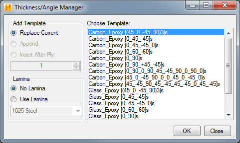
- Clicking the Library button opens the Thickness/Angle Manager window shown below. This window allows you to quickly import a stored thickness/angle template that will define the geometry of a group of plies (i.e., the number and order of plies, the thickness of each ply, and the fiber orientation of each ply). The imported plies will automatically be added to the list of plies appearing in the display area of the New Laminate window. After importing a thickness/angle template into the new laminate, identify the material to be used for each of the plies in the thickness/angle template. The Thickness/Angle Manager window contains three options that control the process of importing a thickness/angle template:
- Add Template - Select the location where the plies of the imported thickness/angle template will be inserted into the existing laminate. "Replace Current" simply replaces all existing plies with the plies of the imported thickness/angle template. "Append" adds the plies of imported thickness/angle template to the end of the existing list of plies. "Insert After Ply" adds the plies of imported thickness/angle template immediately after a specific ply from existing list of plies.
- Lamina - Select a single material that will be used for all of the plies in the thickness/angle template. The default setting "No Lamina" simply adds the thickness/angle template to the laminate layup without specifying a material for any of the plies. The "Use Lamina" option allows you to apply a single material type to all plies in the thickness/angle template.
- Choose Template - The Thickness/Angle Manager window provides a list of all stored thickness/angle templates. Simply select the desired thickness/angle template from the list.

- Delete
- To delete selected ply(s) from the new laminate layup, press the Delete button.
- Clear
- To permanently remove all plies from the display area of the New Laminate window, press the Clear button. This allows you to quickly "start over".
- Save
- To save the new laminate material in the material database, click the Save button in the New Laminate window. The saved laminate will be visible in the material data file tree.
- Ply Stack Visualization - The ply stack visualization window allows you to view a model of your laminate. The stack visualization updates dynamically as you add or remove plies, specify ply thicknesses, or modify fiber orientations. The ply stack visualization is a great way to verify that the laminate is defined correctly.