Compute the transverse deflection of a simply supported or clamped plate.
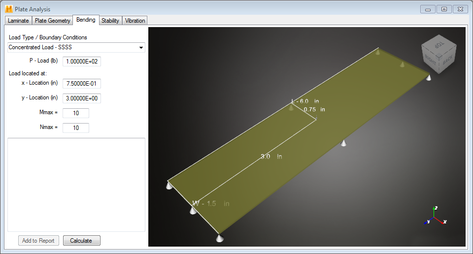
To perform a bending analysis of a laminated composite plate under transverse load, select the Bending tab from the Plate Analysis window. Once the Laminate and Plate Geometry tabs have been defined, complete the following five steps in the Bending tab (see below):

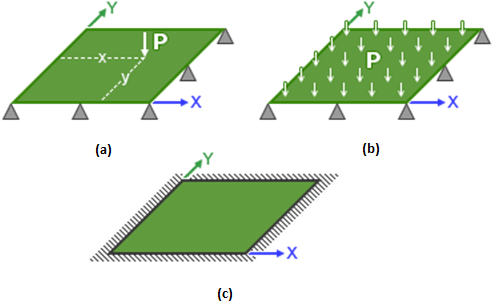
- Specify Loading and Boundary Conditions - The Loading Type / Boundary Conditions drop-down menu contains three different combinations of transverse loading and boundary conditions that can be selected:
- Concentrated Load - SSSS represents a concentrated transverse load acting on a plate with simply-supported boundary conditions on all four of its edges (see part a of the image below).
- Uniform Load - SSSS represents a uniform distributed transverse load acting on a plate with simply-supported boundary conditions on all four of its edges (see part b of the image below).
- Uniform Load - CCCC represents a uniform distributed transverse load acting on a plate with clamped boundary conditions on all four of its edges (see part c of the image below).
- Specify Magnitude of Transverse Loading - The P -Pressure box is used to specify the magnitude of the applied transverse load. When using the "Uniform Load - SSSS" condition or the "Uniform Load - CCCC" condition, you must specify a pressure to define the transverse load. When using the "Concentrated Load - SSSS" condition, you must specify a net force to define the transverse load.
- Specify X, Y Location Where Solution is Computed - The x-Location and y-Location boxes are used to specify the x, y location where the solution (i.e., the transverse deflection and the bending moments) will be computed during the plate bending analysis. Note, when the "Concentrated Load - SSSS" condition is used, the concentrated force is assumed to be applied at the same point where the solution is calculated. The image of the plate will update as you specify the x and y locations.
- Specify Number of Modes to use in the Double Sine Series Solution - The M max and N max boxes are used to specify the number of sine modes used in the global X and global Y directions, respectively, in representing the transverse deflection and transverse loading (see Eqs. 6.1). As the integer values of mmax and nmax are increased, the transverse deflection is represented more accurately. In most cases, mmax = nmax = 10 provides a reasonably accurate solution. However, the solution is obtained very efficiently, so even mmax = nmax = 100 returns a solution rapidly.
- Calculate Results - After specifying all of the problem definition data and solution control data, click Calculate to compute the plate bending solution. The solution is displayed in the display window. It includes the transverse deflection and the resultant moments Mx, My, and Mxy computed at the user-specified point of interest in the plate.
