Create and save the new bolt
- In the
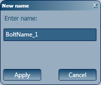
Parameters tab, click the New button next to the Name field drop-down list. Enter the name of your new bolt and click Apply.
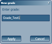
- Create a new grade, by clicking the New button next to the Grade field drop-down list, type a new name and click Apply.
- From the Diameter drop-down list, choose a value.
Note: You can also create a new diameter value, using the New button next to the Diameter field drop-down list, if you cannot find a suitable one in the existing list.

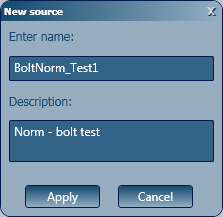
- Create a new source (norm) by clicking the New button next to the Source field drop-down list, type a new name and a description and click Apply.
- Move to the
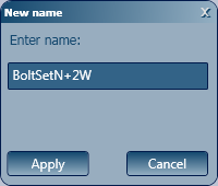
Set tab and create a new bolt assembly by clicking the New button next to the Name of bolt assembly field drop-down list, type an explanatory name (e.g. BoltSetN+2W, which stands for a bolt set with 1 nut (N) and 2 washers (2W) and click Apply.
- At this point, you can save your new bolt in the database. Click Apply to do so.
Define the bolts in the bolt assembly
In the Bolts tab:
- Add values for the bolt head parameters (A, B) and the number of corners.
 Note: If you your bolt needs to have a round head, type 0 (zero) for the number of corners.
 - In the table, define the length, weight and part name for each bolt belonging to a specific assembly. In this example, 5 different bolt lengths will be defined for the BoltName_1 bolt with a 16 mm diameter - these lengths are 40mm, 45mm, 75mm, 80mm and 130mm.
Note: The values entered in this table will be used in the Bill of Materials when choosing to have the bolt assembly (BoltSetN+2W) displayed into exploded components.

- Click Apply to save your settings.
Create new nut and washer types for the assembly
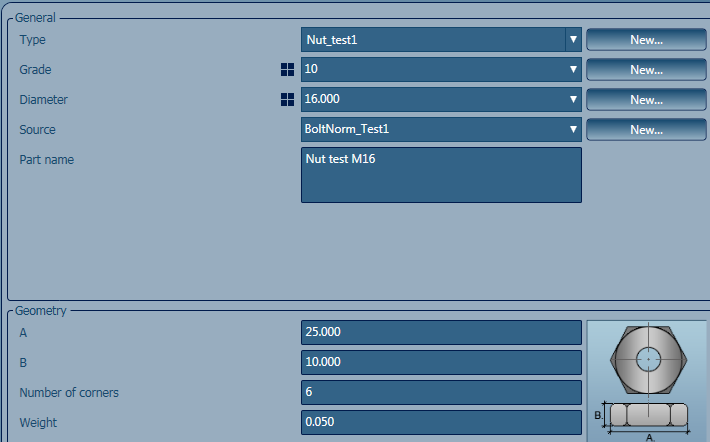
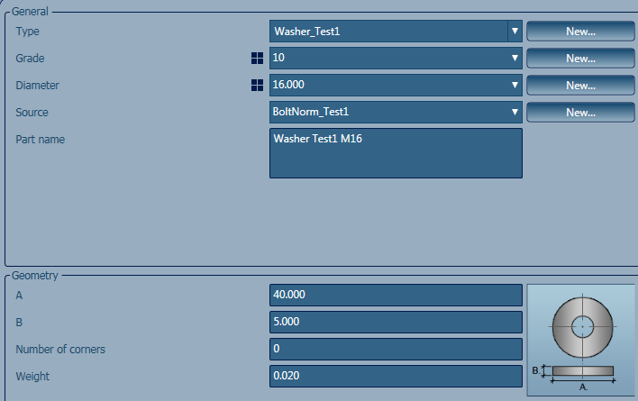
See Create and Customize Nut and Washer Types. The following configuration was made, to suit the bolt that is defined in this example:
- Nut configuration
- Washer configuration
After defining your new nut and washer types:
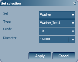
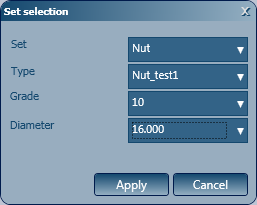
- Go back to the Set tab of BoltName_1 and add the nut and washers to your bolt assembly.
- In the Set tab, use the plus sign (+) to add nuts and washers to your assembly.
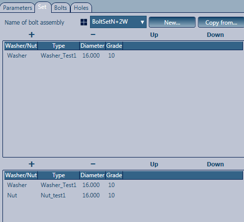
For this example, one washer was added for the top part of the bolt and one washer and one nut were added for the bottom part of the bolt:
Define the rules for the bolts
Go back to the Parameters tab and define the rules to be used for the bolt lengths entered in the first table of the Bolts tab.
Rules are defined following certain norms. So for this specific example, the norm for a bolt body 16mm thick (M16) has the following pattern, where L is the entire bolt body length and lg is the bolt grip length (between the washers and nuts):
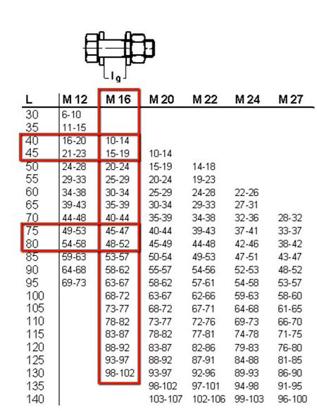
In the Bolts tab table, the defined bolt lengths were 40mm, 45mm, 75mm, 80mm and 130mm. Therefore, the rules will be defined for those specific bolt lengths.
To create a rule in the Management Tools table, you need to find a pattern in the norm.
According the norm used in this example, the bolt lengths increase by 5mm and so do the grip lengths, until the bolt length reaches 75mm. Therefore, the minimum grip length for the bolt lengths between 40mm and 75mm will be 10mm, with a step for the bolt length increase of 5mm and a maximum grip length of 47mm.
When the bolt length reaches 75mm, the grip length increase is no longer 5mm, but shorter. This means that the pattern changes and you need to define a different rule for the bolt lengths starting with 80mm.
The two rules that result from this norm patterns will be:
Rule 1: for bolt lengths between 40mm and 75mm, the minimum grip length is 10mm, the bolt length increase (delta) is 5mm and the maximum grip length is 47mm.
Rule 2: for bolt lengths starting with 80mm, the minimum grip length is 47mm, the bolt length increase (delta) is still 5mm and the maximum grip length is 102mm.

After entering the rules in the Parameters tab, click Apply.
You can check the accuracy of your rules in the Bolts tab, second table, for the lengths defined in the first table.

 (Update defaults) button in the Tools tab
  Tools panel to refresh the database to include your new settings.
You can now use your new bolt in the 3D model as needed:
