Learn about the sets of properties that you can customize in the Management Tools bolt type properties tabs.
When you select a bolt type, a set of properties is displayed on the right side of the application window. These properties are split into four tabs:
- The Parameters tab
- The Set tab
- The Bolts tab
- The Holes tab
The Parameters tab
| Name | The name of the bolt type. |
| Grade | The bolt grade value. |
| Diameter | The bolt diameter value. |
| Source | The norm or the standard of a specific bolt. This property can be used in the BOM editor. |
| Explodable check box |
Controls the way the bolt is listed in the Bill of Materials. If checked, each of the bolt assembly components (bolt, nut, and washer) will be displayed in the BOM lists, with the part name you give to the bolt. If not checked, the bolt assembly will be displayed as an assembly in the BOM lists. |
|
|
Filters the grade and diameter lists to display only values specific to a certain bolt class. |
| The Copy from… button | Copies the parameters from already created bolts and adds them to the current one. |
The rules table contains the rule definitions used for the automatic bolt length calculation.
The Set tab
Here you can select and define the components of the bolt assembly: the bolt, the nuts and the washers. Add the nut and washer combinations by using the "+" sign and "Up" and "Down" to arrange the nuts and washers in the assembly.
The Bolts tab
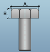
This tab contains the geometric parameters for the bolts.
| A, B |
The values that define the bolt head dimensions.  |
| Number of corners | The value that defines the number of corners of a bolt head. |
| To calculate length automatic (for this type) check box |
When checked, the bolt types entered in the first table of the Bolts tab will follow the rules defined in the Parameters tab, populating the second table in the Bolts tab with the specific information according to those rules. |
The first table in this tab contains the defined bolt length and weight values specific for the valid combinations of the set, name, grade and diameter.
The second table contains information about bolts created by the length rules defined in the Parameters tab.
The Holes tab
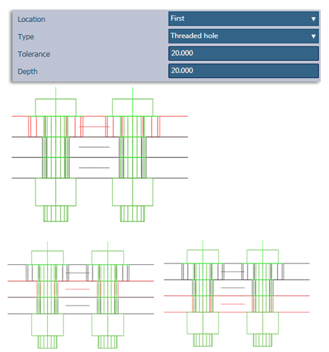
In this tab you can configure the way the holes are created by default, when the bolts are inserted in the 3D model.
There are 3 types of holes you can choose from, each type having a set of parameters.
| Location |
This sets which element the specific configured type of hole will be created on, when the bolts go through several elements. If you select First / Last, the hole type set here will be created only on the first / last element through which the bolts go. By default, round holes will be created through the rest of the elements. If you choose All, the specific configured hole type will be created on all the elements.  |
| Type | The hole type (e.g. round, threaded, countersunk.) |
| Tolerance | The value defining the distance between the bolt body and the hole edge. |
| Depth |
The value that defines the depth of the hole through the element (not available for round holes). Note: For countersunk holes, this parameter defines the depth of the bolt head.
|
| Angle | The value that defines the angle at which the bolt head hole pierces the element. This parameter is available only for countersunk holes.
 |
| Head diameter | The value that defines the diameter of the bolt head hole. This parameter is available only for countersunk holes. |
 (Inactive)
 (Active)