We have provided more control over the appearance of welding symbols.
Weld Type Symbol Scaling
- Weld type symbols.
- Contour symbols.
- Stagger symbols (ISO and ISO based standards only).
- Peripheral symbol (GB standard only).
- Field weld symbol.
- Tail symbol.
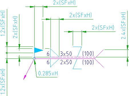
We have now introduced the ability to specify a scale factor, so that you can resize these elements independently of the text height. The illustration shown below is an ISO welding symbol, where the dimensions of each element is specified as a formula. H is the text height and SF is the scale factor.
Process Gap
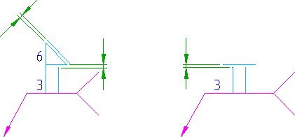
In previous versions of AutoCAD Mechanical, we did not give you the ability to control the gap between the first and second processes, or the gap between a process and a contour. We have now exposed the process gap setting to let you control these gaps.
Saving to Older Versions
- All elements associated with the scale factor setting revert to the default size corresponding to the version you saved to.
- The gaps between the welding processes return to the default setting corresponding to the version you saved to
Since the scale factor and process gap information is stripped away, visual fidelity of welding symbols is lost when you save to an older version.