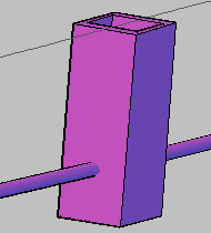
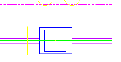
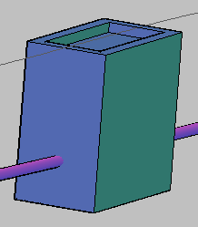
In this exercise, you will insert the new vault part into a AutoCAD Civil 3D pipe network, and investigate how it behaves as a pipe network structure.
This exercise continues from Exercise 4: Finalizing the Part.
- Make sure that you have closed the Part Builder environment from the previous exercise.
- In the AutoCAD Civil 3D window, click Quick Access toolbar

 . Navigate to the tutorials drawings folder. Open the drawing Part Builder-3a.dwg. This drawing contains a simple sanitary sewer pipe network.
 - In the Toolspace Settings tab, expand Pipe Networks
 Parts Lists, and then right- click Sanitary Sewer and then click Edit.
 - Click the Structures tab. Right-click Sanitary Sewer and then click Add Part Family.
- Check the box next to Vault 5106-LA with Top 5106-TL3-332. Click OK. The part family is added to the parts list.
- Right-click Vault 5106-LA with Top 5106-TL3332, and then click Add Part Size. Note the new part size that has been included.
- Click OK to add a single part size with the default values. Expand Vault 5106-LA with Top 5106-TL3-332. Note the new part size that has been included.
- Click OK. Click the sanitary sewer manhole in any of the drawing views. Right-click and then click Swap Part.

- Expand Vault 5106-LA with Top 5106-TL3-332, and select the part beneath it. The part now is displayed as the vault in 3D view, but still is displayed as a manhole in plan view.

- Click the structure in any of the views. Right-click and then click Structure Properties.
- Click the Information tab. Click the black triangle next to the edit button, and select Create New.
- Click the Information tab. Enter Model for Name.
- Click the Profile tab. Click Display as solid.
- Click the Display tab. Set the visibility for Model 3D Solid to On.
- Click OK twice. Note the change to the appearance of the structure in plan view. The vault structure now is displayed with its actual dimensions.

- Click the vault structure. Right-click and select Structure Properties. Click the Part Properties tab.
- Change the following:
- Frame Length = 108
- Frame Width = 48
- Inner Structure Length = 120
- Inner Structure Width = 60
- Click OK. Note the change to the structure in the drawing. The structure has been updated with the new dimension properties.

- Save and close the drawing.