In this exercise, you will add the final model and size parameters that will allow the part geometry to be modified in AutoCAD Civil 3D.
This exercise continues from Exercise 3: Building the Vault Box.
- Continue from the previous exercise in the Part Builder environment. Click the View tab
 Views panel
  SW Isometric. Next you will link the Size Parameters that will be available in AutoCAD Civil 3D with the actual dimensions of the Top Section. This view makes it easier to perform the next few steps.
 - Right-click Size Parameters
 Edit Configuration. Click the New button at the top of the Edit Part Sizes dialog box. The New Parameter dialog box is displayed.
 - Click Frame Height, and then click OK. The Frame Height (SFH) parameter is added.
- Scroll to the right until you see the SFH column. Click Constant in the SFH column and change it to List. Click the drop-down arrow button next to Parameter Configuration, and select Values. The values for each parameter are shown.
- Click the value cell in the SFH column, and then click the Edit button. Add the values 8,12, and 16 to the list and then click OK. Set the value of SFH to 8. This parameter will now be available as three sizes in AutoCAD Civil 3D.
- Click OK. Click Save Part Family. This updates the Model Parameters to include the Size Parameters.
- Right-click Size Parameters and then click Edit Values. Set the following values:
- SBSL: 120
- SBSW: 60
- SFL: 108
- SFW: 48
- SBSH: 48
Click the Update Model button in the Edit Part Sizes dialog box toolbar. Click OK. This updates the model parameter values to match the size parameters.
- Right-click Model Parameters and then click Edit. Set the value of LenB1 to SFH. Click Close. LenB1 is the dimension that represents the depth of the outer frame extrusion.
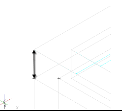
- Expand Modifiers. Right-click Box and turn off the visibility. Turn on the visibility of Box Outside and Box Inside. This displays the appropriate modifiers for dimensioning.
- Right-click Model Dimensions and then click Add Distance. Click the outer box extrusion in the drawing, then click a location for the dimension.
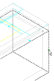
Dimension LenB3 is created.
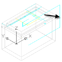
- Repeat this step for the inner box extrusion.
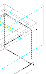
Dimension Len B4 is created.
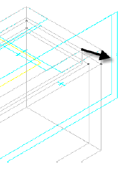
- Right-click Model Parameters, click Edit, and set the equation for LenB3 to LenB4 + Fth (floor thickness). While the Model Parameters dialog box is displayed, set the value for Fth to 4. Len B3 is the length of the Box Outer extrusion which is set to the Box Inner extrusion length plus the thickness of the floor.
- Equate dimension LenB4 to SRS-SFH (rim to sump height - frame height). Change the value of SRS to 48.
- Equate SBSH to LenB1+LenB3 Click Close. SBSH is the Structure Height parameter. Note:
This parameter will be visible in AutoCAD Civil 3D, but will not be able to be edited by the user. It is important that this parameter does not evaluate to zero. If it does, the part will not display in AutoCAD Civil 3D.
- Make the following changes to Size Parameters.
- Fth
- Change to List
- Set List to 4,8,12
- Set the value to 4
- Wth
- Change to List
- Set list to 4,8,12
- Set the value to 4
- Add SIL (Inner Structure Length)
- Change to List
- Set List to 12 inch increments from 48 to 120
- Set value to 120
- Add SIW (Inner Structure Width)
- Change to List
- Set List to 12 inch increments from 36 to 60
- Set value to 60
- SRS
- Change to Range
- Set Minimum Value to 36
- Set Maximum Value to 120
- Set Default Value to 72
Fth = Floor thickness and Wth = Wall thickness. These parameters will be available in three sizes, and will be editable structure properties in AutoCAD Civil 3D.
SIL=Inner Structure Length and SIW=Inner Structure Width. These parameters will be available in a number of sizes at 12-inch increments. These are the key structure properties that control the length and width of the part in AutoCAD Civil 3D.
RS=Rim to Sump height. This is a key structure property that will allow the depth of the structure to be controlled in AutoCAD Civil 3D.
Click Save Part Family when you are finished so that the part is saved, and the Model Parameters are updated to include the new Size Parameters.
- Fth
- Right-click Size Parameters and then click Edit Values. Change the following:
- SBSL=120
- SBSW=60
- SFL=108
- SFW=48
Click the Update Model button in the Edit Part Sizes dialog box toolbar, and then click OK.
- Right-click Model Parameters and then click Edit. Make the following changes in the Equation column for each of the following. Make the changes in the order shown.
- LenA1: SIL + (2*Wth) - LenA1 is the model dimension for the outer length of the box. It has been set to the Inside Structure Length (SIL) plus the thickness of each wall (2 x Wth).
- LenA2: SIW + (2*Wth) - LenA2 is the model dimension for the outer width of the box. It has been set to the Inside Structure Width (SIW) plus the thickness of each wall (2 x Wth).
- SBSL: LenA1 - SBSL and SBSW are important structure properties that have been set to the actual model dimensions.
- SBSW: LenA2
- SVPC: SFH + 6 - The vertical pipe clearance (SVPC) has been set to the frame height (SFH) plus six inches.
- Expand Work Planes
 Rim
Rim Geometry. Right-click Fixed Center
 Visible. The rim center point is displayed in the drawing.
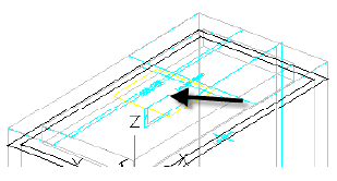
- Expand Autolayout Data. Right-click Layout Data and then click Set Placement Point. Use the NODE object snap to select the Fixed Center point. The placement point is much like an insertion point for an AutoCAD block.
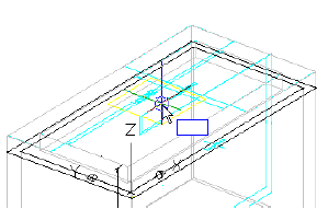
- Expand Modifiers. Turn on the visibility of Frame and Box. Turn off all other modifiers.
- Click Generate Bitmap.
- Click SW Isometric View. Click OK. A bitmap image has been generated for the part catalog.
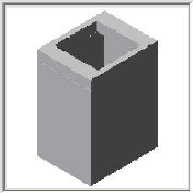
- Click Save Part Family. Exit the Part Builder Environment.
To continue this tutorial, go to Exercise 5: Using the New Part.