In this exercise, you will use the feature line stepped offset command to generate a simplified footprint from which to grade.
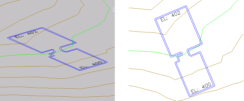
The drawing you will use in this tutorial displays a building pad in two vertically arranged viewports. In the right viewport, the building pad is shown in plan view. You will design the building pad in the right viewport. In the left viewport, the building pad is displayed in model view. You will use this viewport to see the status of the design as you work.
Create a stepped offset feature line
- Open Grading-6.dwg, which is located in the tutorials drawings folder.
- On the command line, enter OffsetGapType. Enter 1 as the value.
The OffsetGapType variable controls how potential gaps between segments are treated when closed polylines, such as the building pad feature line, are offset. Setting this variable to 1 fills the gaps with filleted arc segments; the radius of each arc segment is equal to the offset distance.
- Click tab
 panel
panel  drop-down
  Find.
Find. - On the command line, enter 1.5 as the offset distance.
- In the right viewport, click the blue feature line representing the building pad when prompted to select a feature line.
- Click outside the building pad when prompted to specify the side to offset.
- At the command line, enter G to specify a grade value. Enter -1 as the grade.
- Press Enter to end the command.
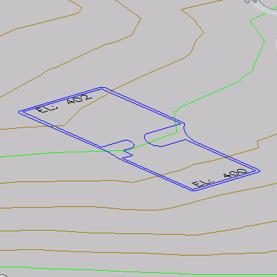
The stepped offset feature line is displayed. Notice that in the left viewport, on the left side of the ramp, the curve of the stepped offset feature line is not well formed. Because it is an independent feature line, you can use the feature line editing tools to refine the solution.

Add fillets to the feature line
- Click tab
 panel
panel  Find.
Find. - Click the offset feature line when prompted to select an object.
- On the command line, enter R to specify a radius for the fillet. Enter 15.000 as the radius value.
- On each side of the ramp, click a sharp inside corner of the offset feature line.
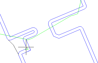
When you move the cursor over the feature line, a green triangle highlights the corners that can be filleted and a preview fillet is displayed. See the following image for an example of a corner to click.

The fillet is applied to the feature line. In the left viewport, notice that the fillet uses the elevations from the existing feature line and smoothly interpolates the elevations along the length of the fillet.

- Press Enter twice to end the command.
To continue this tutorial, go to Exercise 2: Grading from a Building Footprint to a Surface.